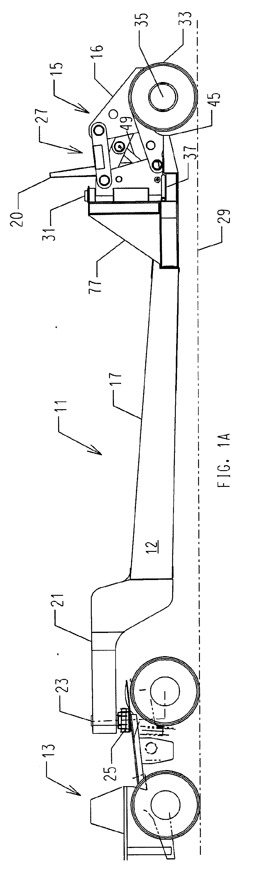
[0016]In order to convert the trailer from its transport position to the loading position, the pair of axle wheel assemblies is first lifted from the transport position to a raised position, using a hydraulic
system associated with the axle wheel assembly linkage mechanism. By lifting them, the axle wheel assemblies automatically unfasten from their locking engagement with the trailer chassis pockets, freeing the axle wheel assemblies to move laterally about a vertical pivot axis associated with the axle wheel assembly linkage mechanism. Raising the axle wheel assemblies causes the back end of the trailer chassis to lower to the ground and into the trailers loading position.
[0017]While the trailer chassis is in its loading position (i.e., the axle wheel assemblies in their raised position), the axle wheel assemblies are rotated about the vertical axes so as to clear the axle wheel assemblies from the back end of the trailer chassis and loading ramps are lowered. The load (e.g., heavy machinery) is then moved onto the trailer chassis from the lowered back of the trailer chassis with loading ramps while in its loading position. After the load is completely loaded onto the trailer chassis the loading ramps are raised and, each of the axle wheel assemblies is rotated about the
vertical axis so as to bring the axle wheel assembly back to its raised position behind and in line with the trailer chassis. The axle wheel assemblies are then lowered so that each of them automatically locks into the trailer chassis pockets, thereby preventing
lateral movement of the axle wheel assemblies.
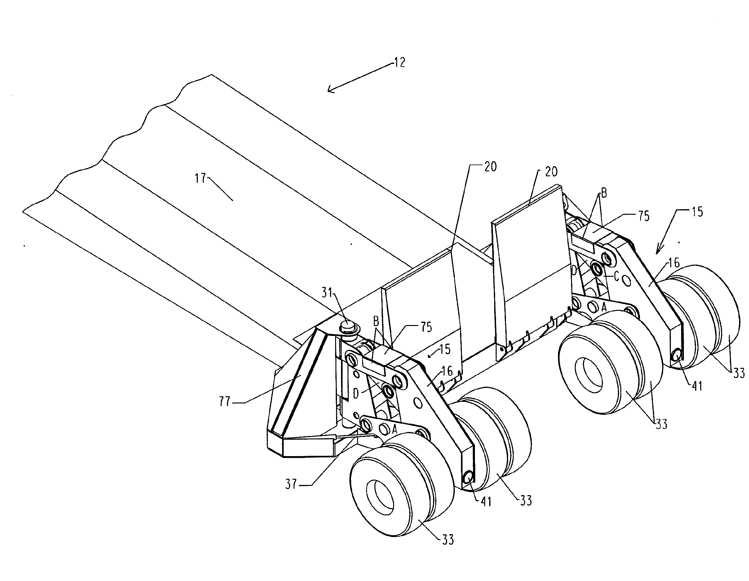
[0018]Each axle wheel assembly supports wheels and tires on both sides of the axle wheel assembly carrier frame where the weight of the trailer chassis and its load transfers from the trailer chassis to the wheels and tire axles. Also, the wheel and tire axle on each side of the pivot has room for two or more wheels and tires, making the wheel and tire axle
safer than either two tires cantilevered to one side of the of the wheel and tire axle or a single tire on each side of the wheel and tire axle as a single tire
blow out could cause trailer
instability. Two pivots on the trailer chassis connect each axle wheel assembly to the trailer chassis. As the trailer transports a load, each of the wheel and tire axles is free to rotate about a
horizontal axis extending longitudinally from front to rear of the trailer chassis, enabling wheels and tires on opposing sides of each wheel and tire axle to rotate about the axis. The rotation allows the wheels and tires to respond to changes in the elevation of the
terrain between the tires on each common wheel and tire axle. Preferably, the axle of each wheel and tire axle moves independently of the other axle and each axle preferably supports four wheels and tires, with two of the wheels and tires on one side of a center support of the wheel and tire axle and the other two on the other side. This arrangement of the rear wheels assists in distributing the weight of the load as the trailer navigates uneven
terrain and tends to cancel any appreciable sideways torque on either the trailer chassis or the wheel and tire axles. In effect, the opposing wheels and tires, and corresponding wheel and tire axle rotate about the horizontal axle pivot in opposing directions to compensate for changes in ground elevation across the width of the trailer as the trailer moves.
[0019]By positioning the axle wheel assemblies behind the trailer chassis when they are in their transport positions, a wider wheel base is more easily achieved then if axles and wheels extended from the sides of the trailer chassis. Plus, the relatively wide wheel base offered by positioning the axle wheel assemblies behind the trailer chassis spreads out the load over a greater ground area lessening ground bearing pressures, allowing the lowboy trailer to operate in difficult ground conditions such as soft and / or wet ground conditions. The overall width of the two, in-line axle wheel assemblies with the trailer in the transport position is substantially wider than either the trailer deck or the piece of equipment being transported, resulting in a stable and
safe operation. The overall width of the two trailer axle wheel assemblies, however, is considerably less than normal haul road widths found in off-highway work sites such as open-pit mines.
[0022]Additionally the deck of the trailer is preferably angled in line with the trailer's loading ramps in order to minimize any apex in the loading surface in the area where the ramp transitions to the trailer deck. Minimizing or eliminating the loading apex then minimizes or eliminates any concentration of load on both the trailer chassis and on any undercarriage of the equipment being loaded during the trailer loading process, which also minimizes or eliminates any potential equipment
instability as equipment is loaded onto the trailer.
[0023]The trailer preferably uses standard OEM spindles, bearings, hubs, and brakes such as
Caterpillar truck rear spindles for the
truck axle model nos. 773F, 775F, 777F, 785C, 789C, 793C and 797B. The different models differ by their weight ratings and, therefore, the selection of a particular spindle model depends on the desired weight rating for the trailer. These spindles have mechanical oil cooled disc brakes that provide substantial braking capacity. When combined with the brakes of the
tractor, substantial braking capacity results.

