Method and apparatus for transitioning a heavy equipment hauling rear loading trailer between transport and loading positions

a technology for heavy equipment and trailers, applied in the field of trailers, can solve the problems of cumbersome and time-consuming loading process, difficult loading of equipment onto trailers, and extreme force on both the edge of trailers and undercarriages, and achieve the effect of minimizing or eliminating loading apex, and minimizing or eliminating load concentration

Active Publication Date: 2011-05-31
HAGENBUCH LEROY G
View PDF22 Cites 7 Cited by
  • Summary
  • Abstract
  • Description
  • Claims
  • Application Information

AI Technical Summary

Benefits of technology

[0016]In order to convert the trailer from its transport position to the loading position, the pair of axle wheel assemblies is first lifted from the transport position to a raised position, using a hydraulic system associated with the axle wheel assembly linkage mechanism. By lifting them, the axle wheel assemblies automatically unfasten from their locking engagement with the trailer chassis pockets, freeing the axle wheel assemblies to move laterally about a vertical pivot axis associated with the axle wheel assembly linkage mechanism. Raising the axle wheel assemblies causes the back end of the trailer chassis to lower to the ground and into the trailers loading position.
[0017]While the trailer chassis is in its loading position (i.e., the axle wheel assemblies in their raised position), the axle wheel assemblies are rotated about the vertical axes so as to clear the axle wheel assemblies from the back end of the trailer chassis and loading ramps are lowered. The load (e.g., heavy machinery) is then moved onto the trailer chassis from the lowered back of the trailer chassis with loading ramps while in its loading position. After the load is completely loaded onto the trailer chassis the loading ramps are raised and, each of the axle wheel assemblies is rotated about the vertical axis so as to bring the axle wheel assembly back to its raised position behind and in line with the trailer chassis. The axle wheel assemblies are then lowered so that each of them automatically locks into the trailer chassis pockets, thereby preventing lateral movement of the axle wheel assemblies.
[0018]Each axle wheel assembly supports wheels and tires on both sides of the axle wheel assembly carrier frame where the weight of the trailer chassis and its load transfers from the trailer chassis to the wheels and tire axles. Also, the wheel and tire axle on each side of the pivot has room for two or more wheels and tires, making the wheel and tire axle safer than either two tires cantilevered to one side of the wheel and tire axle or a single tire on each side of the wheel and tire axle as a single tire blow out could cause trailer instability. Two pivots on the trailer chassis connect each axle wheel assembly to the trailer chassis. As the trailer transports a load, each of the wheel and tire axles is free to rotate about a horizontal axis extending longitudinally from front to rear of the trailer chassis, enabling wheels and tires on opposing sides of each wheel and tire axle to rotate about the axis. The rotation allows the wheels and tires to respond to changes in the elevation of the terrain between the tires on each common wheel and tire axle. Preferably, the axle of each wheel and tire axle moves independently of the other axle and each axle preferably supports four wheels and tires, with two of the wheels and tires on one side of a center support of the wheel and tire axle and the other two on the other side. This arrangement of the rear wheels assists in distributing the weight of the load as the trailer navigates uneven terrain and tends to cancel any appreciable sideways torque on either the trailer chassis or the wheel and tire axles. In effect, the opposing wheels and tires, and corresponding wheel and tire axle rotate about the horizontal axle pivot in opposing directions to compensate for changes in ground elevation across the width of the trailer as the trailer moves.
[0019]By positioning the axle wheel assemblies behind the trailer chassis when they are in their transport positions, a wider wheel base is more easily achieved then if axles and wheels extended from the sides of the trailer chassis. Plus, the relatively wide wheel base offered by positioning the axle wheel assemblies behind the trailer chassis spreads out the load over a greater ground area lessening ground bearing pressures, allowing the lowboy trailer to operate in difficult ground conditions such as soft and / or wet ground conditions. The overall width of the two, in-line axle wheel assemblies with the trailer in the transport position is substantially wider than either the trailer deck or the piece of equipment being transported, resulting in a stable and safe operation. The overall width of the two trailer axle wheel assemblies, however, is considerably less than normal haul road widths found in off-highway work sites such as open-pit mines.
[0022]Additionally the deck of the trailer is preferably angled in line with the trailer's loading ramps in order to minimize any apex in the loading surface in the area where the ramp transitions to the trailer deck. Minimizing or eliminating the loading apex then minimizes or eliminates any concentration of load on both the trailer chassis and on any undercarriage of the equipment being loaded during the trailer loading process, which also minimizes or eliminates any potential equipment instability as equipment is loaded onto the trailer.
[0023]The trailer preferably uses standard OEM spindles, bearings, hubs, and brakes such as Caterpillar truck rear spindles for the truck axle model nos. 773F, 775F, 777F, 785C, 789C, 793C and 797B. The different models differ by their weight ratings and, therefore, the selection of a particular spindle model depends on the desired weight rating for the trailer. These spindles have mechanical oil cooled disc brakes that provide substantial braking capacity. When combined with the brakes of the tractor, substantial braking capacity results.

Problems solved by technology

However, even with the low elevation of the trailer deck that gives the trailer a characteristic look and its “lowboy” name, loading equipment onto the trailer is difficult if the equipment is driven up the ramp and up over onto the lowboy trailer, which is typically done when the equipment is self-powered.
In each of these cases, however, loading heavy earth moving equipment onto the trailer by driving the equipment up a ramp and onto the deck of the trailer creates an extreme force on both the edge of the trailer and the undercarriage of the earth moving equipment as the entire weight of the earth moving equipment transfers to the trailer at the trailer's edge during the equipment's movement up the ramp and over onto the trailer.
For front-loaded lowboys, the tractor hitching apparatus or gooseneck is unhooked from the trailer chassis proper for loading and then rehooked up to the trailer chassis proper after the trailer chassis is loaded, making the loading process both cumbersome and time consuming.
However, often the weight of the machinery loaded on to the trailer is too much for a conventional wheel and axle assembly where the wheels and axles of the assembly extend cantilevered from the sides of the trailer for supporting the wheels and tires as in the Armstrong, Bates and Smith patents.
The weight of the load carried by the trailer creates large moment arm torques on the cantilevered axles because of the outboard positions of the wheels and tires.
The stresses on the axle created by these large moment arms makes it difficult for such trailers to carry the heaviest of loads such as the largest earth moving equipment.
But the location of the axle and wheel assemblies obstructs access to the rear trailer edge for loading.

Method used


Image

  • Method and apparatus for transitioning a heavy equipment hauling rear loading trailer between transport and loading positions
  • Method and apparatus for transitioning a heavy equipment hauling rear loading trailer between transport and loading positions
  • Method and apparatus for transitioning a heavy equipment hauling rear loading trailer between transport and loading positions

Examples


Embodiment Construction

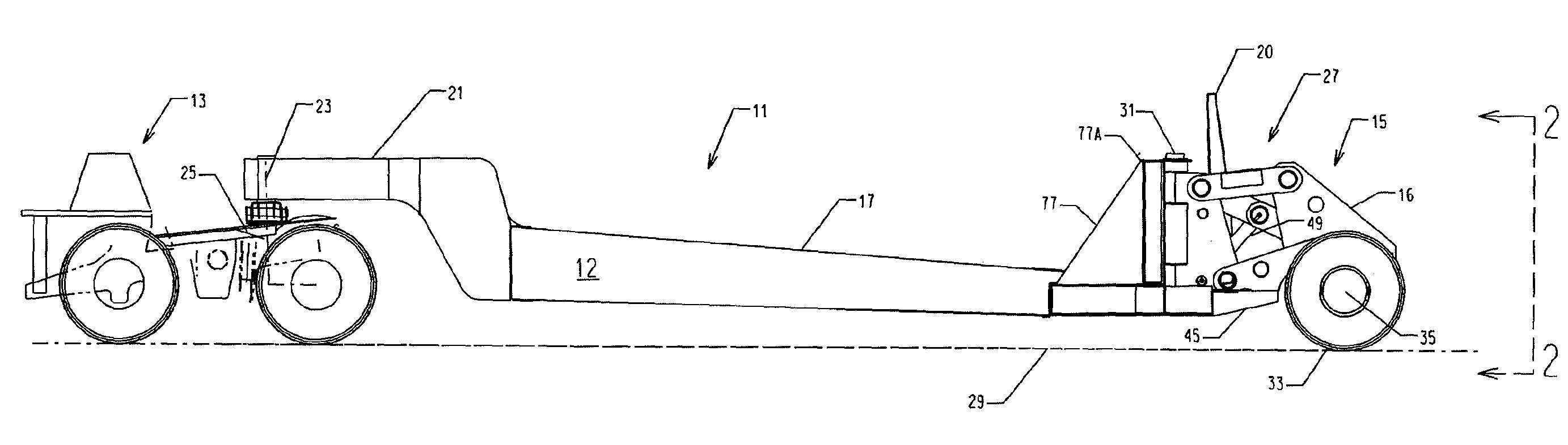
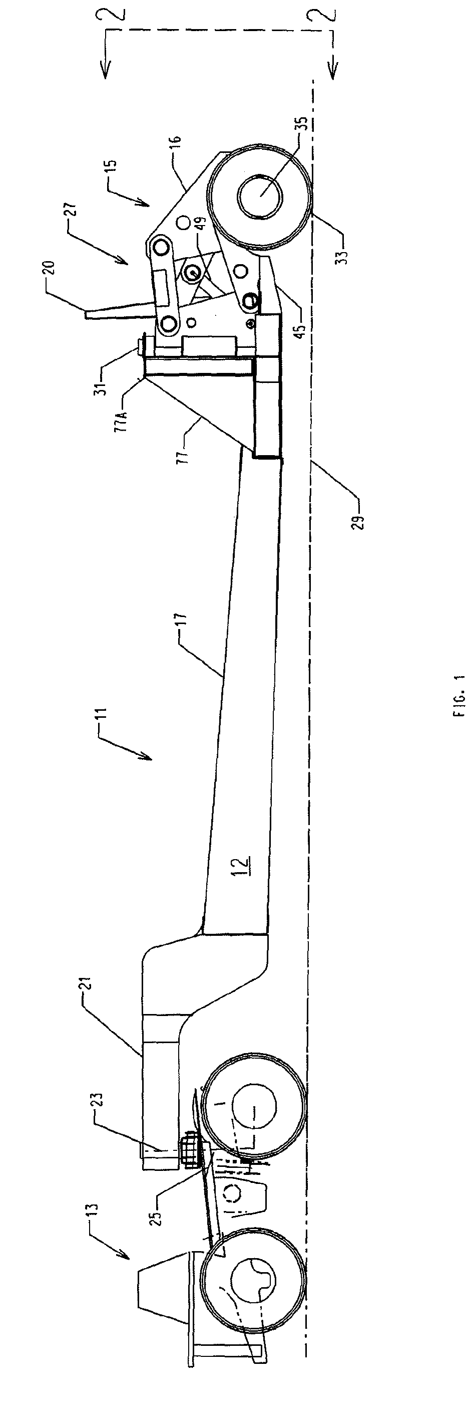
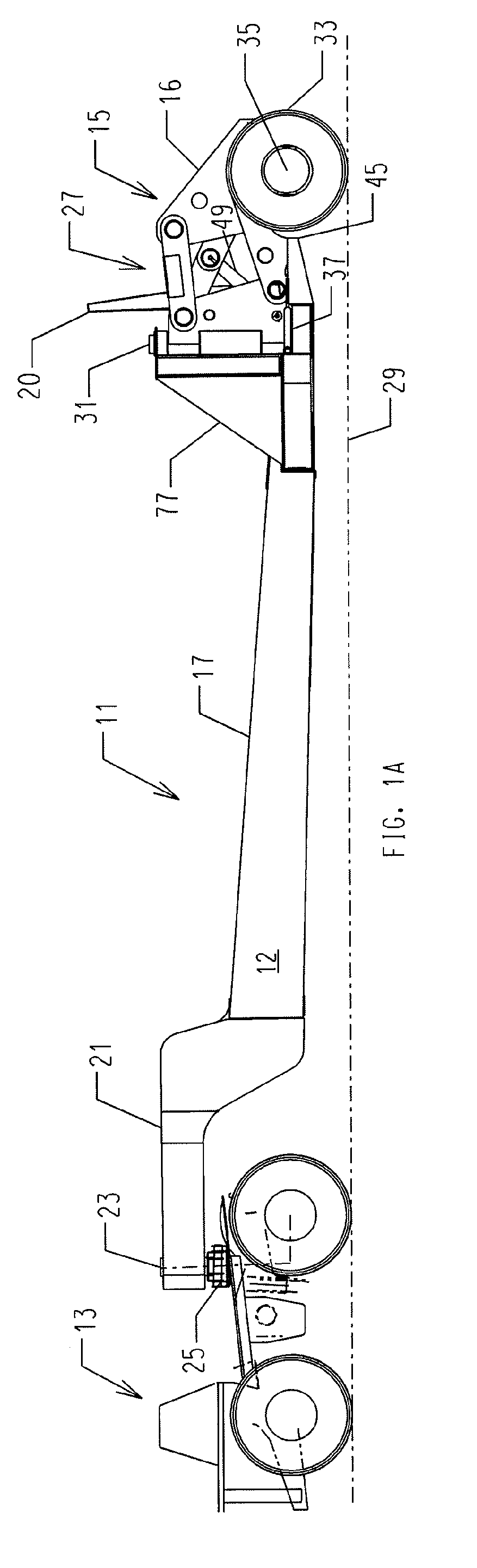
[0061]Turning to the drawings and referring first to FIGS. 1A through 1O, a trailer 11 is supported by a tractor 13 at the front of the trailer 11 and by a pair of axle wheel assemblies 15 at the back of the trailer 11. In the following description of the axle wheel assemblies 15, reference is often made to one of the axle wheel assemblies 15 with the understanding that each of the axle wheel assemblies 15 is the mirror image of the other. Those skilled in the art of designing trailers of the type illustrated and described herein will appreciate that the following description referencing one of the axle wheel assemblies 15 applies equally well to the other axle wheel assembly 15.

[0062]The trailer 11 includes trailer chassis 12, having a deck 17 for carrying a load such as a self-propelled, excavator 19 shown in FIGS. 1E through 1O. In the illustrated embodiment, the deck 17 of the trailer chassis 12 is angled so as to provide a substantially flat single planar surface between the de...


PUM


Abstract

A rear loading lowboy trailer is described having a pair of rear wheel assemblies mounted to a chassis of the trailer for movement between transport and loading positions such that the wheel assemblies are aligned across a back of the chassis when they are in the transport position and raised and positioned outwardly when the chassis is in the loading position. A linkage mechanism moves each of the wheel assemblies in both horizontal and vertical directions so as to move each of the wheel assemblies between the transport and loading positions. Each linkage mechanism automatically fastens the wheel assembly to the chassis of the trailer when the wheel assembly is moved to its transport position.

Description

CROSS-REFERENCE TO RELATED APPLICATIONS[0001]This patent application claims the benefit of U.S. Provisional Patent Application Nos. 60 / 983,082, filed Oct. 26, 2007, and 61 / 098,716, filed Sep. 19, 2008, each of which is incorporated by reference in its entirety and for everything it teaches.FIELD OF THE INVENTION[0002]The present invention is directed to a rear loading heavy equipment hauling lowboy trailer and a method of using it. In particular, the invention concerns a trailer for transporting heavy loads such as earth-moving machinery and apparatus and methods for loading and unloading the heavy loads to and from the lowboy trailer.BACKGROUND OF THE INVENTION[0003]Lowboy trailers are often used to transport heavy machinery from one work site to another. These trailers are typically flatbed carriers with a gooseneck connection to a tractor. This type of trailer is commonly called a “lowboy” because the trailer is characterized by a low elevation of the trailer's deck. The low deck...

Claims


Application Information

Patent Timeline
Patent Type & Authority Patents(United States)
IPC IPC(8): B62D53/06B60P1/00
CPCB60P3/062
Inventor HAGENBUCH, LEROY G.
Owner HAGENBUCH LEROY G
Why Eureka
Try Eureka