Linear motor and stage apparatus, exposure apparatus, and device manufacturing method using the same

Inactive Publication Date: 2005-03-22
CANON KK
View PDF1 Cites 29 Cited by
  • Summary
  • Abstract
  • Description
  • Claims
  • Application Information

AI Technical Summary

Benefits of technology

The present invention has been made in view of the problems of the prior art that have not yet been solved, and has as its object to provide a linear motor which has an excellent driving performance with a small thrust ripple (thrust variations) while requiring a low cost and providing a high

Problems solved by technology

As the entire shape of each magnet is not a simple rectangular parallelepiped, each permanent magnet is

Method used


Image

  • Linear motor and stage apparatus, exposure apparatus, and device manufacturing method using the same
  • Linear motor and stage apparatus, exposure apparatus, and device manufacturing method using the same
  • Linear motor and stage apparatus, exposure apparatus, and device manufacturing method using the same

Examples


Embodiment Construction

The preferred embodiments of the present invention will be described with reference to the accompanying drawings.

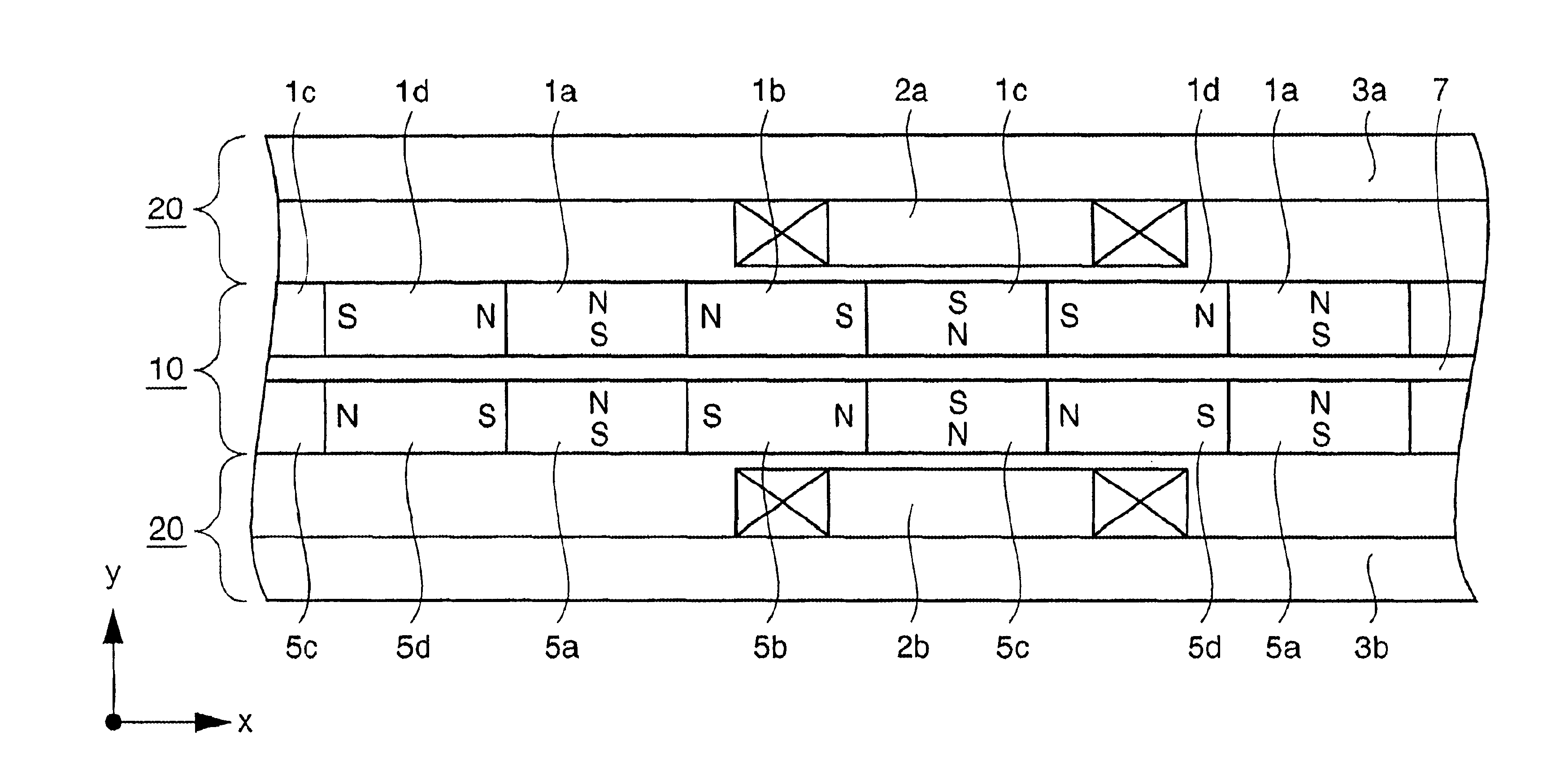
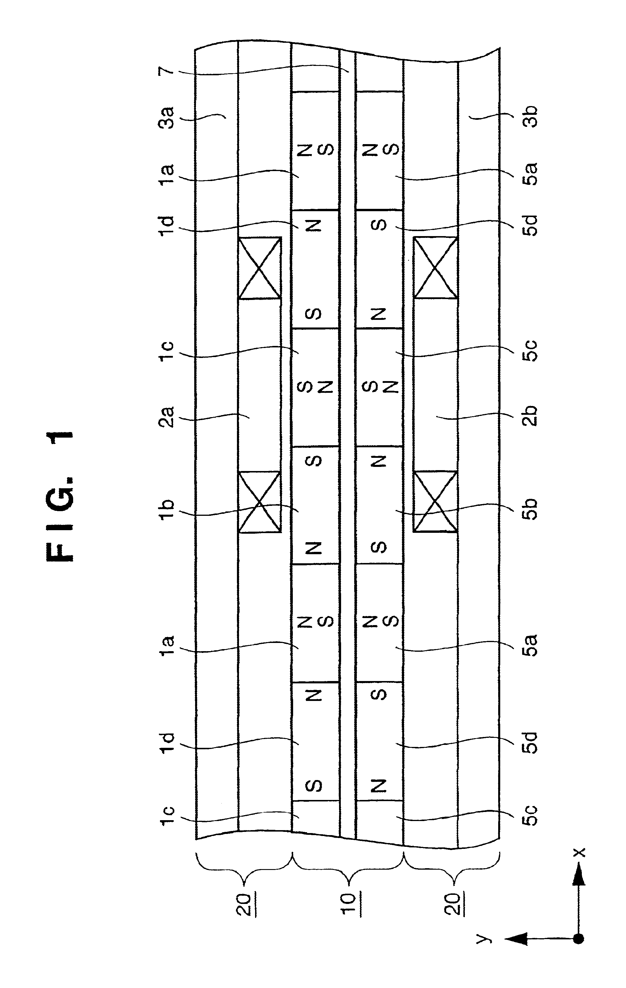
FIG. 1 shows an embodiment of the invention. In this linear motor M, a first permanent magnet group of first magnets 1a to 1d are arrayed in the x-axis direction and integrally connected on a holding member 7. The first permanent magnet group has the first magnets 1a and 1c arrayed such that their polarization directions are periodically opposite, and the second magnets 1b and 1d arrayed adjacent to the first magnets 1a and 1c such that their polarization directions are periodically opposite. A second permanent magnet group is arrayed on the other side of the holding member 7. A linear motor movable element 10 is thus formed. In the same manner as the first permanent magnet group, the second permanent magnet group has third magnets 5a and 5c arrayed such that their polarization directions are periodically opposite, and fourth magnets 5b and 5d arrayed adjacent to the thir...


PUM


Abstract

A linear motor includes a magnet array having a plurality of first magnets arrayed such that polarization directions thereof are periodically opposite, and a plurality of second magnets arrayed such that polarization directions thereof are periodically opposite and intersect those of the first magnets. The linear motor further includes an electromagnetic coil disposed to oppose the magnet array to generate a Lorentz force in cooperation with the magnet array and a yoke integrated with the coil at a first side opposite to a second side of the coil disposed opposite to the magnet array.

Description

FIELD OF THE INVENTIONThe present invention relates to a linear motor suitably used as, e.g., a driving source for a stage apparatus mounted on an exposure apparatus or the like for the manufacture of a semiconductor device or the like, and a stage apparatus, an exposure apparatus, and a device manufacturing method using the same.BACKGROUND OF THE INVENTIONFIG. 12 shows the arrangement of the permanent magnets of a linear motor according to one prior art device. FIG. 12 shows only one of two permanent magnet groups opposing each other through a holding member 7. Permanent magnets 110a and 110b alternately arrayed on the holding member 7 have a non-rectangular parallelepiped shape with corners being cut off. The permanent magnets 110a and 110b are arrayed such that their magnetisms (N and S poles) are alternately opposite. Also, the thicknesses and widths of the permanent magnets 110a and 110b are so adjusted as to generate an ideal sine wave magnetic field in a space between opposin...

Claims


Application Information

Patent Timeline
IPC IPC(8): G03F7/20H02K41/03G12B5/00G03F7/22G03F9/00H01L21/027
CPCH02K41/03G03F7/70758
Inventor UCHIDA, SHINJI
Owner CANON KK
Why Eureka
Try Eureka