
Post-processing device and image forming system

a post-processing device and image forming technology, applied in the direction of electrographic process equipment, optics, instruments, etc., can solve the problems of deteriorating productivity of the post-processing device, such as the number of products of printed matter per hour, and the part of jammed paper has been already discharged, so as to prevent deterioration in productivity

Inactive Publication Date: 2019-04-18
KONICA MINOLTA INC
View PDF0 Cites 5 Cited by
  • Summary
  • Abstract
  • Description
  • Claims
  • Application Information

AI Technical Summary

Benefits of technology

The purpose of this patent is to stop productivity from decreasing when a recovery-printed sheet is cut to get a printed item.

Problems solved by technology

However, there is a case where a part of the jammed paper has been already discharged as a printed matter.
Therefore, productivity of the post-processing device (for example, the number of products of printed matters per hour) largely deteriorates.
However, in a case where the printed matters are not allowed to be duplicated (for example, variable printed matter on which address on postcard is printed), the overlapping region cannot be originally output as a printed matter.
In this way, since the confirmation by the user takes time and labor, the productivity of the post-processing device is deteriorated.

Method used


Image

  • Post-processing device and image forming system
  • Post-processing device and image forming system
  • Post-processing device and image forming system

Examples


embodiment

[0035]

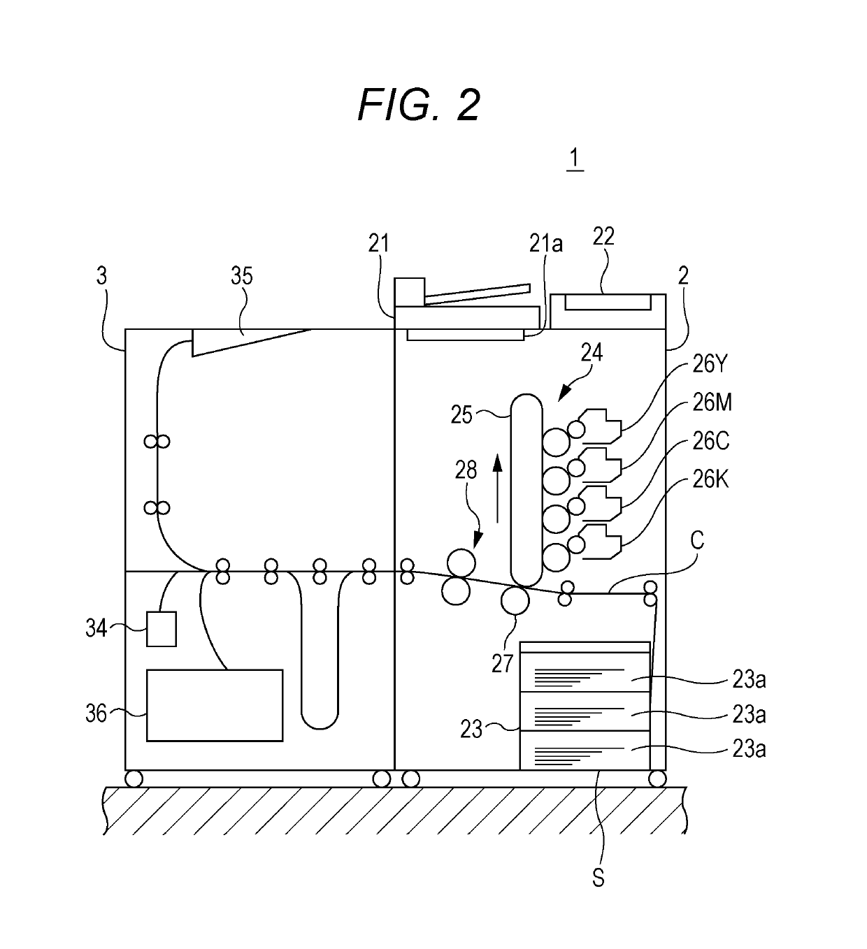
[0036]FIG. 2 is a schematic diagram of an exemplary overall configuration of an image forming system 1.

[0037]The image forming system 1 includes an image forming device 2 and a post-processing device 3.

[0038]The image forming device 2 performs image forming processing of print data received from a personal computer (PC) terminal (referred to as print processing) according to an operation instruction from an operation display 22 provided in the image forming device 2 or a print instruction from the PC terminal which is not shown transmitted via a network. Furthermore, the image forming device 2 can read characters, figures, and the like printed on a sheet S supplied from an automatic document feeder (ADF) 21 and output image data. As an image forming device 2, for example, a copier, a printer, a facsimile, and a combined apparatus combining two or more of these functions can be applied.

[0039]The image forming device 2 employs an electrophotographic method for forming an image b...


PUM


Abstract

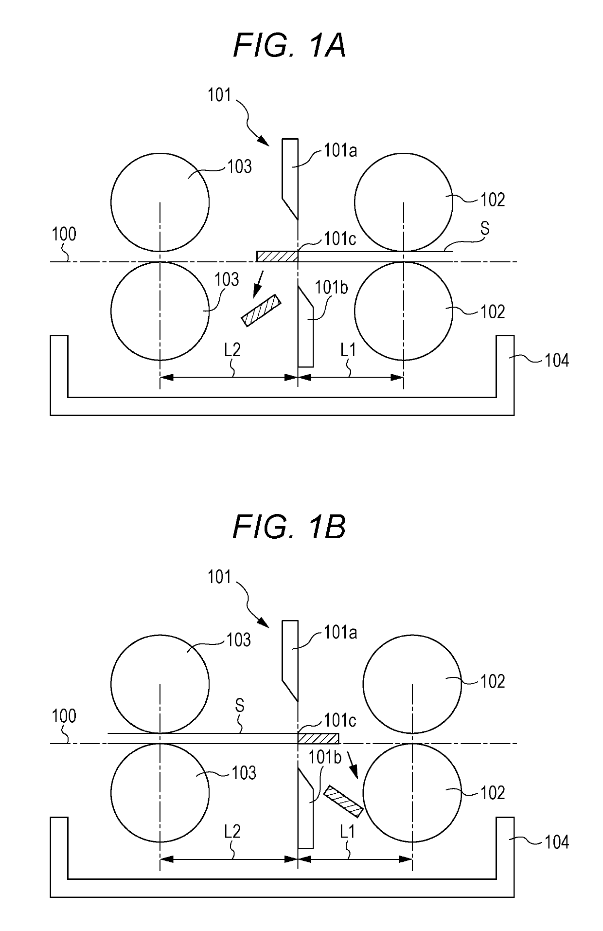
A post-processing device includes: a cutter that performs cutting processing for dividing a printed sheet into a plurality of pieces; and a hardware processor that determines an overlapping region where a content of a recovery-printed sheet on which recovery printing has been performed due to an error which causes the cutting processing to be stopped during the cutting processing by the cutter is overlapped with a content of a printed matter obtained by the cutting processing before the error occurs, and makes the cutter cut the overlapping region of the recovery-printed sheet into pieces larger than the printed matter.

Description

[0001]The entire disclosure of Japanese patent Application No. 2017-200312, filed on Oct. 16, 2017, is incorporated herein by reference in its entirety.BACKGROUNDTechnological Field[0002]The present invention relates to a post-processing device and an image forming system.Description of the Related Art[0003]There is an image forming system including an image forming device which forms an image on a sheet and a post-processing device which performs post processing on the sheet on which the image has been formed by the image forming device. The image forming device and the post-processing device respectively perform image forming processing and post processing according to setting values of various items regarding the image forming processing and the post processing.[0004]The post processing performed by the post-processing device is, for example, cutting processing for creating printed matters (for example, business card, card, and postcard) by dividing a single sheet into a pluralit...

Claims


Application Information

Patent Timeline
Patent Type & Authority Applications(United States)
IPC IPC(8): G03G15/00
CPCG03G15/6523G03G2215/00814
Inventor WAKABAYASHI, HIROYUKI
Owner KONICA MINOLTA INC
Learn More