
Production system and production method

a production system and production method technology, applied in the direction of total factory control, manufacturing tools, inspection/indentification of circuits, etc., can solve the problems of unnecessarily performing detection of bad marks and deteriorating productivity of electronic devices, so as to prevent deterioration of productivity of electronic devices

Active Publication Date: 2022-01-04
JUKI CORP
View PDF3 Cites 0 Cited by
  • Summary
  • Abstract
  • Description
  • Claims
  • Application Information

AI Technical Summary

Benefits of technology

[0008]According to the respective aspects of the present invention, it is possible to prevent deterioration in productivity of an electronic device.

Problems solved by technology

When the plurality of mounting devices individually detect the bad mark, the detection of the bad mark may be unnecessarily executed.
When the detection of the bad mark is unnecessarily executed, the productivity of the electronic device may deteriorate.

Method used


Image

  • Production system and production method
  • Production system and production method
  • Production system and production method

Examples


Embodiment Construction

[0016]Hereinafter, embodiments of the present invention will be described with reference to the drawings, and the present invention is not limited to the embodiments described below.

[0017]Production System

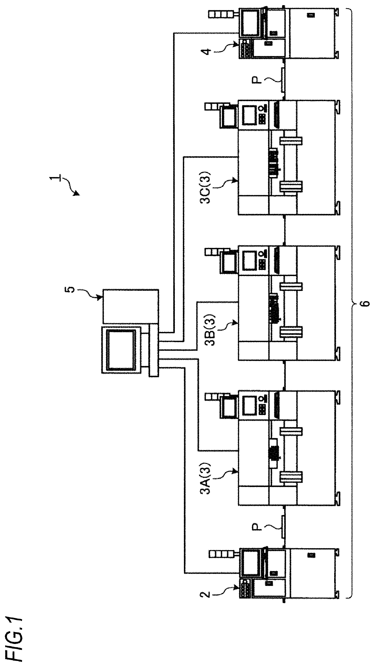
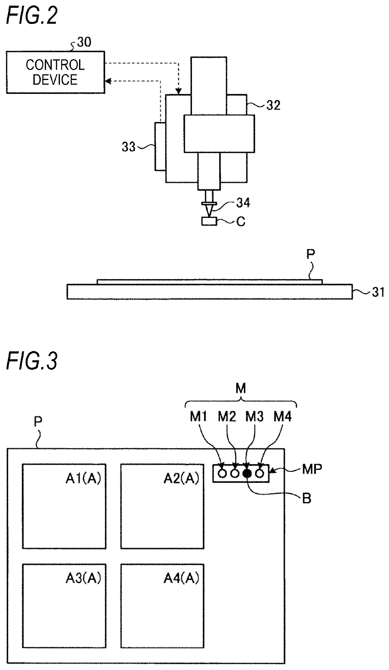
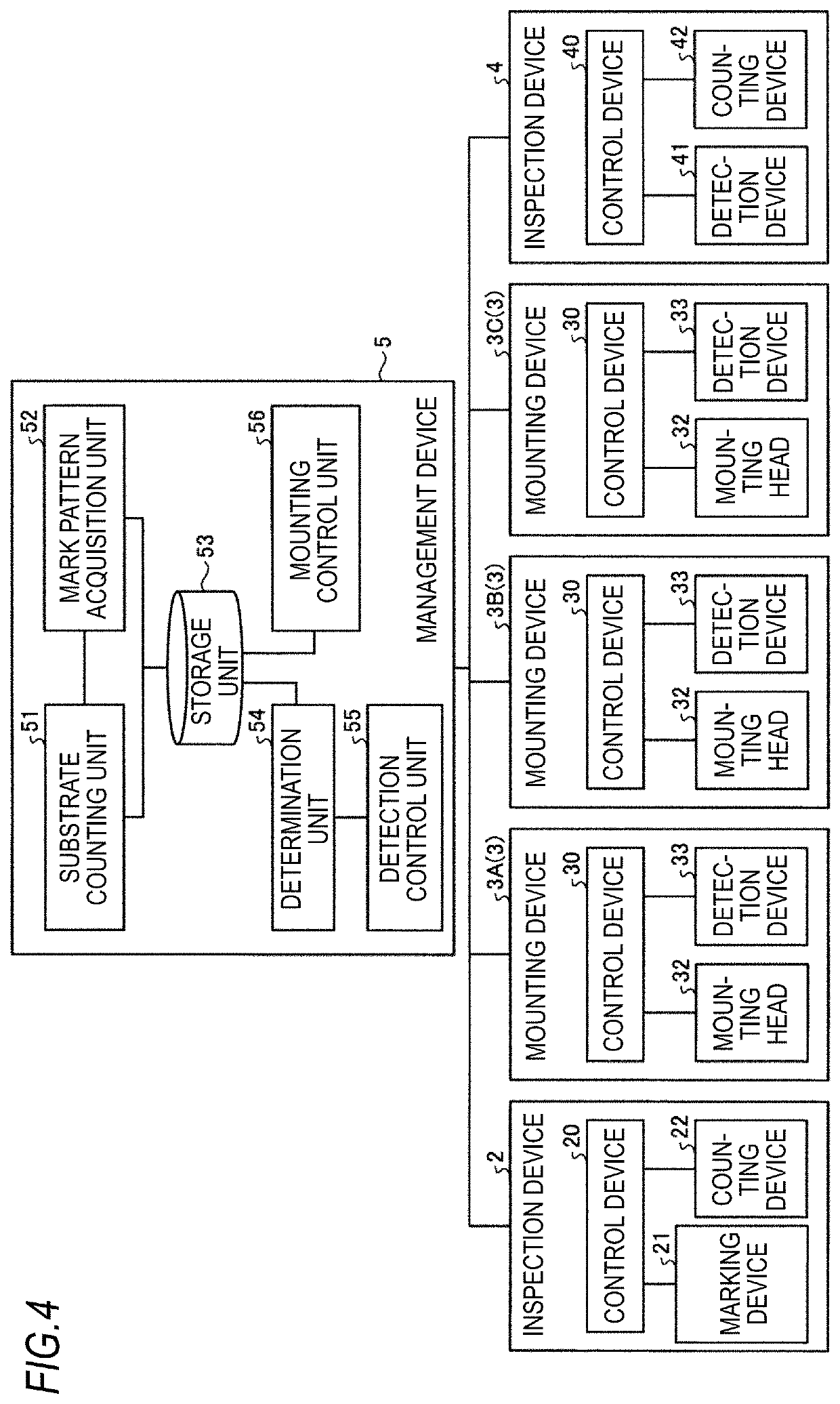
[0018]FIG. 1 is a diagram illustrating a production system 1 according to the embodiment. As illustrated in FIG. 1, the production system 1 includes an inspection device 2, a mounting device 3, an inspection device 4, and a management device 5. A production line 6 for an electronic device is constructed by the inspection device 2, the mounting device 3, and the inspection device 4.

[0019]In the production line 6, a plurality of mounting devices 3 are provided. In the embodiment, the mounting device 3 includes a first mounting device 3A, a second mounting device 3B, and a third mounting device 3C.

[0020]A substrate P is conveyed in the production line 6. The electronic device is produced by conveying the substrate P in the production line 6. In the embodiment, a leading device of the ...


PUM

PropertyMeasurementUnit
automated optical inspectionaaaaaaaaaa
areaaaaaaaaaaa
area M2aaaaaaaaaa

Abstract

A production system includes: a substrate counter configured to count the number of substrates existing in a production line including a mounting device; a mark pattern acquisition unit configured to acquire a mark pattern indicating a pattern of a mark that is provided to each of the plurality of substrates counted by the substrate counter; a determination unit configured to determine whether the respective mark patterns of the plurality of substrates acquired by the mark pattern acquisition unit are the same as each other; and a detection controller configured to control a detection process of the mark pattern by the mounting device based upon a determination result of the determination unit.

Description

CROSS-REFERENCE TO RELATED APPLICATIONS[0001]The present application claims the benefit of priority of Japanese Patent Application No. 2019-055123, filed on Mar. 22, 2019, the content of which is incorporated herein by reference.TECHNICAL FIELD[0002]The present invention relates to a production system and a production method.BACKGROUND ART[0003]In a production system for producing an electronic device, a production line is constructed by a plurality of mounting devices. Before carrying a substrate into the production line, a process of printing cream solder on the substrate and an inspection process of inspecting a printed state of the substrate are executed. When the printed state is defective, a mark referred to as a bad mark is provided on the substrate. JP-A-2006-086281 discloses a technology in which an individual identification number is provided to the substrate and the bad mark is stored in a storage area in association with the individual identification number.[0004]The ind...

Claims


Application Information

Patent Timeline
Patent Type & Authority Patents(United States)
IPC IPC(8): B23P19/00H05K13/04H05K13/08
CPCH05K13/0452H05K13/08Y10T29/5313H05K13/087H05K13/00H05K13/084Y02P90/02H05K13/0812H05K1/0269
Inventor KOGA, HIROYUKI
Owner JUKI CORP
Learn More