Film capacitor and method for manufacturing film capacitor

a film capacitor and film capacitor technology, applied in the direction of capacitor manufacturing, stacked capacitors, fixed capacitor details, etc., can solve the problems of uniform thickness of outer packaging resin, inability to fully exhibit moisture-proof properties, and likely instability of the capacitor unit at the hanging state, so as to prevent deterioration in productivity and suitable coverage

Active Publication Date: 2020-10-06
PANASONIC INTELLECTUAL PROPERTY MANAGEMENT CO LTD
View PDF8 Cites 1 Cited by
  • Summary
  • Abstract
  • Description
  • Claims
  • Application Information

AI Technical Summary

Benefits of technology

[0010]According to the present disclosure, there can be provided a film capacitor and a method for manufacturing the film capacitor that prevent a deterioration in productivity and achieves suitable coverage with the outer packaging resin.

Problems solved by technology

Since the capacitor unit is hung from the holding jig via the connection terminal parts, the connection terminal parts are likely to deform (refer to FIG. 15 in Unexamined Japanese Patent Publication No. 2014-216453), and further the capacitor unit is likely to be unstable at the hanging state.
This may cause to make the thickness of the outer packaging resin non-uniform, and thus functions of the outer packaging resin such as a moisture-proof property may not fully exhibit.

Method used


Image

  • Film capacitor and method for manufacturing film capacitor
  • Film capacitor and method for manufacturing film capacitor
  • Film capacitor and method for manufacturing film capacitor

Examples


first exemplary embodiment

Effects of First Exemplary Embodiment

[0057]As described above, in accordance with the first exemplary embodiment, the following effects are exhibited.

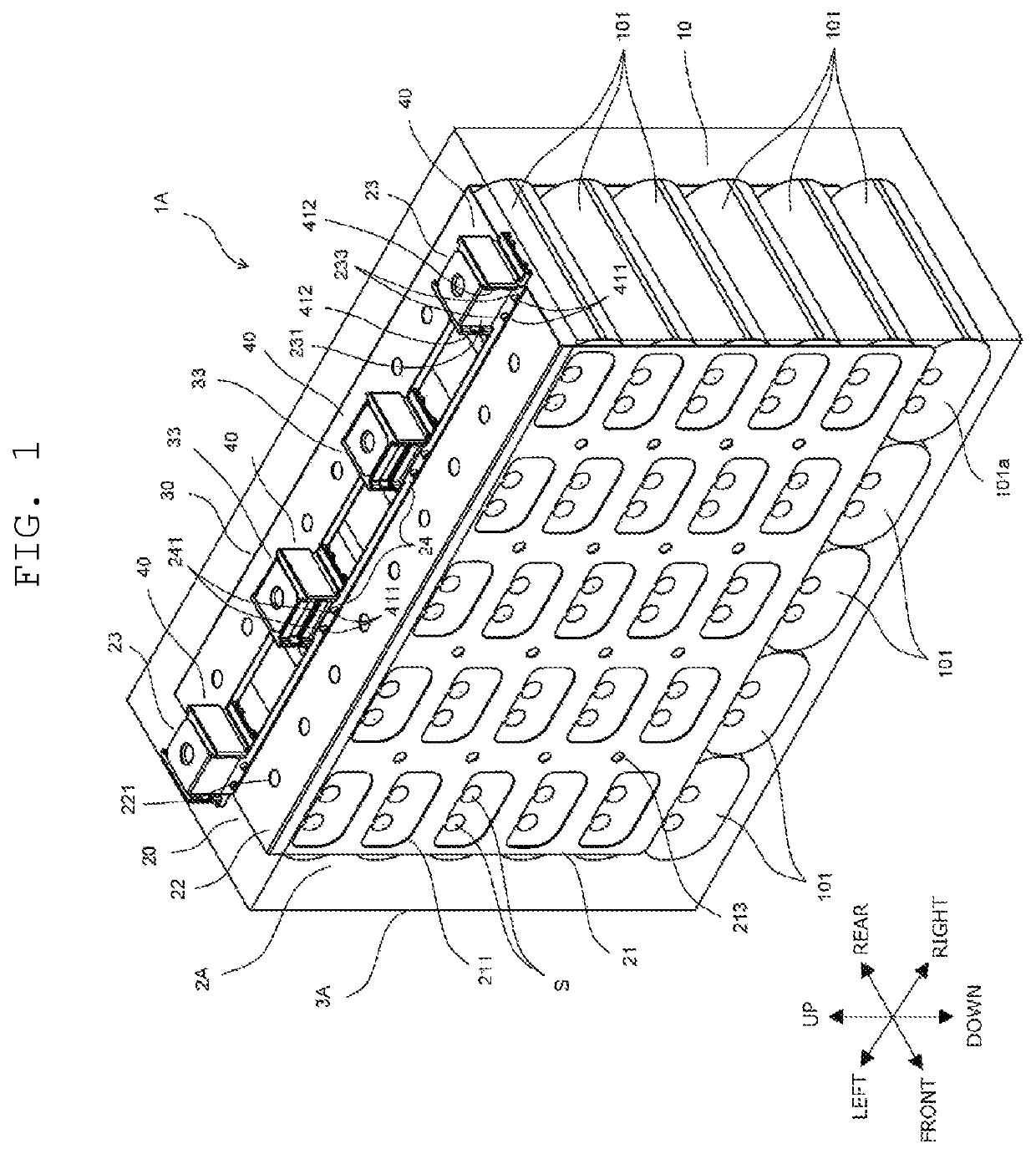
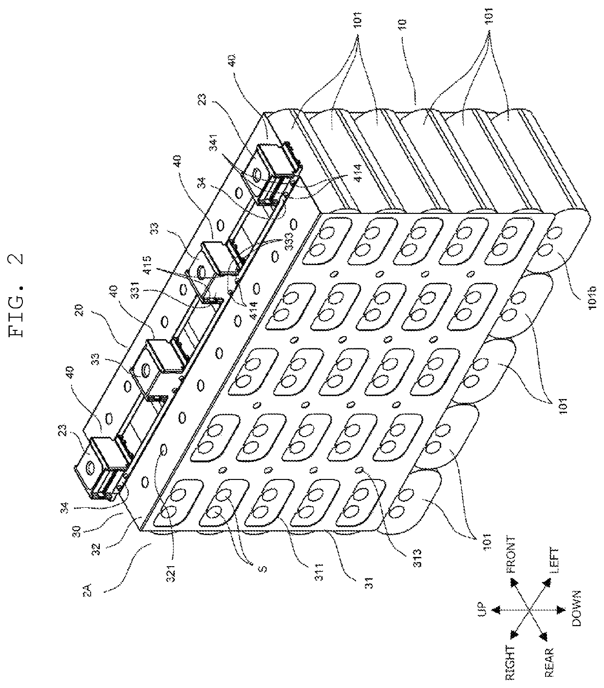
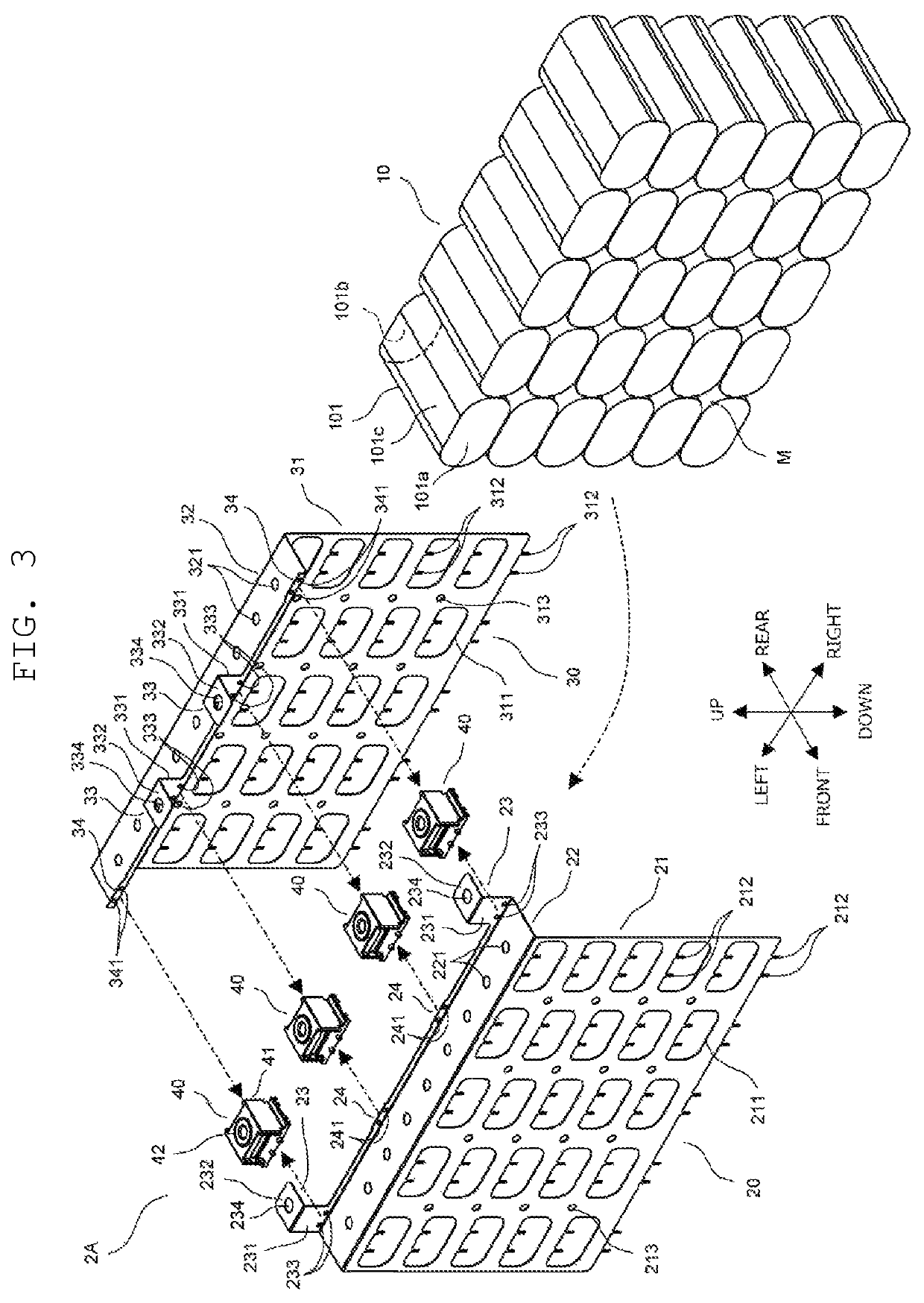
[0058]In capacitor unit 2A, since two fixation portions 40 to which two connection terminal plates 23 of front bus bar 20 and two coupling parts 24 of rear bus bar 30 are coupled, and two fixation portions 40 to which two connection terminal plates 33 of rear bus bar 30 and two coupling parts 24 of front bus bar 20 are coupled can be fixed to holding jig 5, joints to holding jig 5 (fixation portions 40, connection terminal plates 23, 33, coupling parts 24, 34) can have sufficient strength. This makes the joints to holding jig 5 less susceptible to deformation or shaking, thus preventing capacitor unit 2A from being put into inner tank 4a of mold 4 in an inclined state. Therefore, capacitor unit 2A can be suitably covered by outer packaging resin 3A.

[0059]Furthermore, since first terminal parts 231, 331 of connection terminal plates 23,...

second exemplary embodiment

Effects of Second Exemplary Embodiment

[0099]In capacitor unit 2B, since four fixation portions 40 to which four connection terminal plates 53, 62 of first bus bar B1 and four connection terminal plates 72, 83 of second bus bar B2 are coupled can be fixed to holding jig 5, joints to holding jig 5 (fixation portions 40, connection terminal plates 53, 62, connection terminal plates 72, 83) can have sufficient strength. This makes the joints to holding jig 5 less susceptible to deformation or shaking, thus preventing capacitor unit 2B from being put into the inner tank of the mold in an inclined state. Therefore, capacitor unit 2A can be suitably covered by outer packaging resin 3A.

[0100]Furthermore, since first terminal parts 531, 621, 721, 831 of connection terminal plates 53, 62, 72, 83 are in contact with contact faces 41a, 41b of fixation portions 40, respectively, connection terminal plates 53, 62, 72, 83 can be firmly supported by contact faces 41a, 41b, enabling the joints to ho...


PUM


Abstract

A film capacitor includes a capacitor unit, and outer packaging resin covering the capacitor unit. The capacitor unit includes a capacitor group, a first bus bar, a second bus bar, and a fixation portion. The capacitor group includes a plurality of capacitor elements. The first bus bar extracts electricity from the capacitor group. The second bus bar extracts electricity from the capacitor group. The first bus bar and the second bus bar are fixed to the fixation portion. The first bus bar includes a connection terminal part formed at one end of the first bus bar, and the second bus bar includes a connection terminal part formed at one end of the second bus bar. At least one of the connection terminal part of the first bus bar and the connection terminal part of the second bus bar is coupled to the fixation portion.

Description

RELATED APPLICATIONS[0001]This application is a continuation of the PCT International Application No. PCT / JP2016 / 004276 filed on Sep. 20, 2016, which claims the benefit of foreign priority of Japanese patent application No. 2015-200790 filed on Oct. 9, 2015, the contents all of which are incorporated herein by reference.BACKGROUND1. Technical Field[0002]The present disclosure relates to a film capacitor, and a method for manufacturing the film capacitor.2. Description of the Related Art[0003]Unexamined Japanese Patent Publication No. 2014-216453 discloses a film capacitor having a casing-less structure in which an outer packaging resin covers a capacitor unit including a plurality of capacitor elements arranged horizontally and vertically, and a pair of externally-leading terminals (bus bars) connected to metal electrodes (end-face electrodes) formed on both end faces of each of the capacitor elements.[0004]In the film capacitor disclosed in Unexamined Japanese Patent Publication No...

Claims


Application Information

Patent Timeline
Patent Type & Authority Patents(United States)
IPC IPC(8): H01G4/224H01G4/38H02G5/02H01G4/33H01G2/04H01G13/00H01G4/18H01G4/228
CPCH02G5/02H01G4/33H01G2/04H01G4/18H01G13/00H01G4/224H01G4/228H01G4/38Y02T10/70
Inventor KADOMURA, MANATOFUJII, EIZO
Owner PANASONIC INTELLECTUAL PROPERTY MANAGEMENT CO LTD
Why Eureka
Try Eureka