

Flow path structure body, liquid ejecting apparatus, and liquid ejecting method
- Summary
- Abstract
- Description
- Claims
- Application Information
AI Technical Summary
Benefits of technology
Problems solved by technology
Method used
Image

Examples
first embodiment
A. First Embodiment
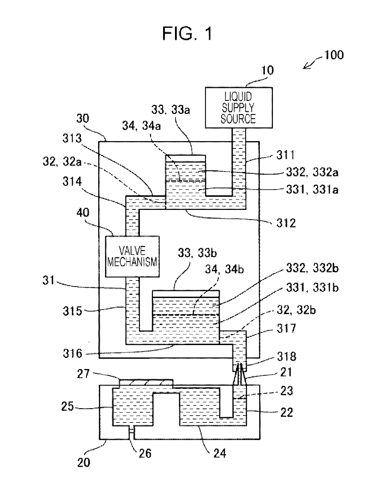
[0021]FIG. 1 is an explanatory diagram illustrating an outline of a liquid ejecting apparatus 100 according to a first embodiment. The liquid ejecting apparatus 100 according to the embodiment is configured as an ink jet printer including a liquid ejecting head 20 that has a nozzle 26 for ejecting ink (liquid) that has been supplied from a liquid supply source 10 and a flow path structure body 30 that is connected between the liquid supply source 10 and the liquid ejecting head 20 and that distributes the ink that has been supplied from the liquid supply source 10 to the liquid ejecting head 20. The flow path structure body 30 is detachably connected to the liquid ejecting head 20. The liquid ejecting head 20 and the flow path structure body 30 will be collectively referred to as a “liquid ejecting unit” in some cases.
[0022]The liquid supply source 10 is an ink supply source. The liquid supply source 10 according to the embodiment is an ink cartridge that is forme...
second embodiment
B. Second Embodiment
[0051]FIG. 6 is an explanatory diagram illustrating an outline of a liquid ejecting apparatus 100b according to a second embodiment. The liquid ejecting apparatus 100b according to the second embodiment is different from the first embodiment (FIG. 1) in the arrangement of the air bubble chamber filter 34 provided in the air bubble chamber 33. In the flow path structure body 30 according to the first embodiment as illustrated in FIG. 1, the air bubble chamber filter 34 is arranged in the horizontal direction during use when the liquid is distributed through the flow path structure body 30, and the space in the air bubble chamber 33 is divided into upper and lower portions in the vertical direction by the air bubble chamber filter 34. Meanwhile, in the flow path structure body 30b according to the embodiment, the air bubble chamber filter 34 is arranged while inclined relative to the horizontal direction as illustrated in FIG. 6 during use when the liquid is distri...
third embodiment
C. Third Embodiment
[0052]FIG. 7 is an explanatory diagram illustrating an outline of a liquid ejecting apparatus 100c according to a third embodiment. The liquid ejecting apparatus 100c according to the third embodiment is different from the first embodiment (FIG. 1) in the structure of the air bubble chamber 33. In the flow path structure body 30 according to the first embodiment as illustrated inFIG. 1, the air bubble chamber 33 is connected directly to the distribution flow path 31. Meanwhile, in the flow path structure body 30c according to the embodiment, the air bubble chamber 33 is connected to the distribution flow path 31 via a branching flow path 333 as illustrated in FIG. 7. The air bubble chamber 33 can store the air bubbles, and the foreign matters that have been formed at the gas-liquid interface can be collected with the air bubble chamber filter 34 even in the flow path structure body 30c in this mode.
D. Other Embodiments
[0053](D-1) In the air bubble chamber 33 as il...
PUM
 Abstract
Description
Claims
Application Information