Printing apparatus and printing method

a printing apparatus and printing method technology, applied in printing, other printing apparatus, etc., can solve the problems of easy fluidification of ink-unabsorbable medium, easy clogging of nozzles, and degrading quality of printed images, so as to achieve the effect of suppressing nozzle clogging

Inactive Publication Date: 2013-10-10
SEIKO EPSON CORP
View PDF4 Cites 3 Cited by
  • Summary
  • Abstract
  • Description
  • Claims
  • Application Information

AI Technical Summary

Benefits of technology

[0007]An advantage of some aspects of the invention is to provide a printing apparatus and a printing method which suppress nozzle clogging.

Problems solved by technology

In addition, the ink landed on the medium of the ink-unabsorbable medium is easily fluidified.
However, heating the medium may also cause a nozzle formation surface of a head to be heated and an ink solvent to be evaporated from the nozzle, thereby the nozzle being easily clogged.
If the nozzle is clogged, an ejection failure occurs in that a predetermined amount of the ink cannot be ejected from the nozzle or ink droplets ejected from the nozzle deviate from their original blowing direction, and thereby a printed image is degraded in quality.

Method used


Image

  • Printing apparatus and printing method
  • Printing apparatus and printing method
  • Printing apparatus and printing method

Examples


embodiment 1

Regarding Nozzle Nz Clogging

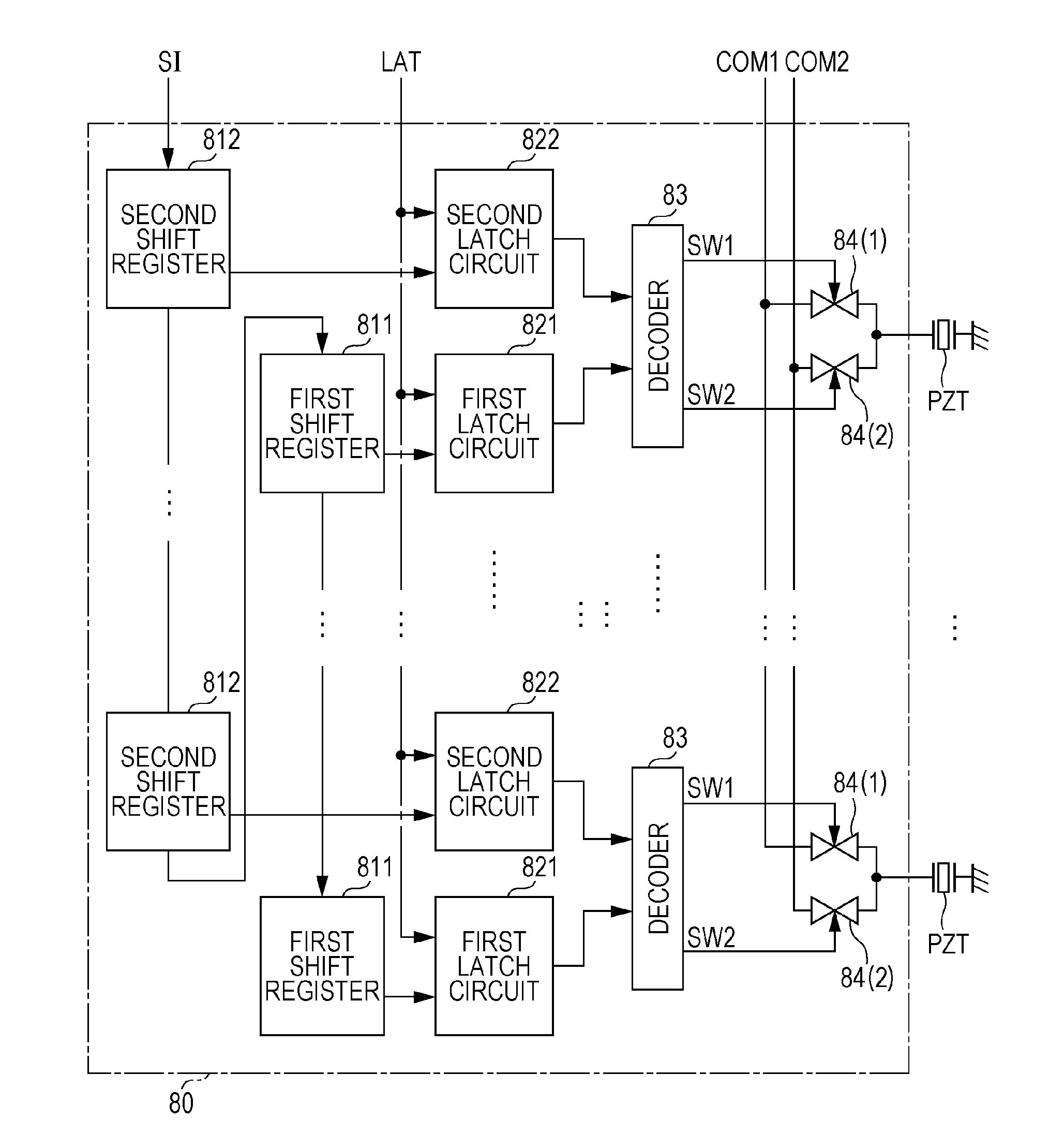
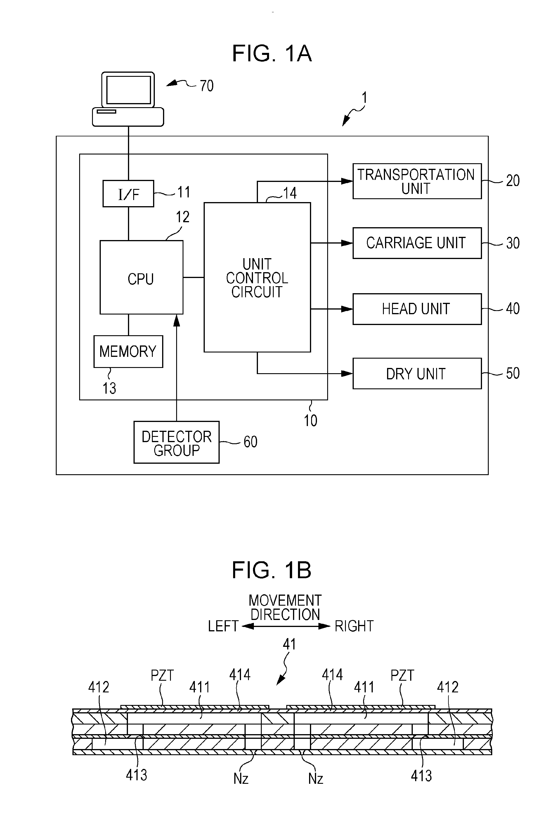
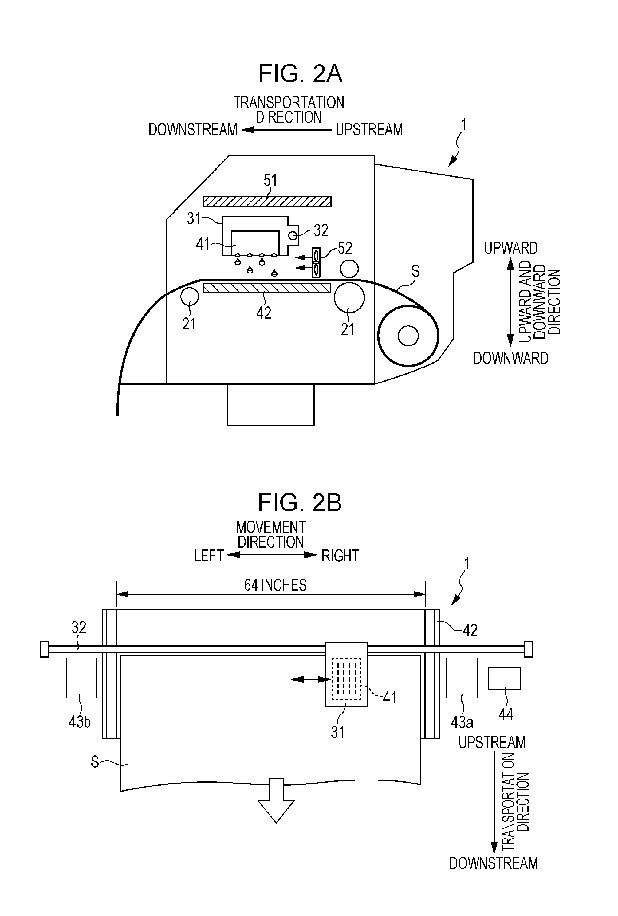
[0086]There is a case where the ink has not been ejected from the nozzles Nz which are not frequently used during the printing over a relatively long period of time, and during the period, the ink solvent is evaporated from the nozzle opening and the ink inside the nozzles Nz or inside the pressure chambers 411 is increased in the viscosity, or a foreign matter such as paper powder or dust is mixed into the nozzles Nz to clog the nozzles Nz. In particular, in the printer 1 of the present embodiment, since the resin ink is ejected onto the ink-unabsorbable medium S, it is necessary to dry the resin ink landed on the medium S in order to suppress the fluidity of the resin ink on the medium S, and accordingly, the high temperature heater 51 for heating the medium S is provided in the printer 1. Therefore, under the influence of the heat from the heater 51 or a radiant heat from the medium S, the nozzle formed surface of the head 41 (lower surface) is heated....

embodiment 2

[0120]FIG. 7 is a view for explaining a printing method according to Embodiment 2. In Embodiment 1, each time the head 41 is moved once in the movement direction, the flushing process is performed in the non-print regions at both sides in the movement direction. In this case, even if the length of the printing target medium S or the length of the image in the movement direction is short, the head 41 has to move from the ink reception unit 43a which is located at the right end in the movement direction to the ink reception unit 43b which is located at the left end in the movement direction. Therefore, in Embodiment 2, depending on the length of the printing target medium S or the length of the image in the movement direction, the movement distance of the head 41 is changed.

[0121]For example, as illustrated in FIG. 7, in a case where the right end of the medium S to transported by being aligned to the right end of the platen 42, the head 41 may print an image while moving to the left ...


PUM


Abstract

A printing apparatus includes a head having a nozzle ejecting an ink having thermoplastic resin particles and a viscosity of 2.1 mPa·s or more at 50° C., a pressure chamber, and a drive element; a medium having ink-unabsorbable characteristics and a length of 64 inches or less in a predetermined direction; a movement mechanism which moves the head in the predetermined direction; a heating unit which heats the medium; and a control unit which causes the movement mechanism to move the head in the predetermined direction and applies a drive waveform generating a pressure change in the ink inside the pressure chamber, to the drive element. The control unit applies a micro-vibration waveform having a size which does not allow the ink to be ejected from the nozzle onto the drive element corresponding to the nozzle if the nozzle does not eject the ink.

Description

[0001]The entire disclosure of Japanese Patent Application Nos. 2012-088184, filed Apr. 9, 2012 and 2013-070352, filed Mar. 28, 2013 are expressly incorporated by reference herein.BACKGROUND[0002]1. Technical Field[0003]The present invention relates to a printing apparatus and a printing method.[0004]2. Related Art[0005]As a printing apparatus, an ink jet printer (hereinafter, referred to as a printer) having a head which ejects an ink from nozzles has been known. In recent years, there has been a demand for printing an image on various types of media such as a sheet of paper, cloth, or plastic film. For example, in order to print the image on an ink-unabsorbable medium such as the plastic film, a printer which uses the ink including thermoplastic resin particles has been proposed (for example, refer to JP-A-2010-221670). By using the ink including the thermoplastic resin particles, it is possible to form a rigid resin film on the medium after the ink is dried and thus to ensure ant...

Claims


Application Information

Patent Timeline
Patent Type & Authority Applications(United States)
IPC IPC(8): B41J2/045
CPCB41J2/04541B41J2/04581B41J2/04596B41J2/04593B41J2/04588
Inventor SATO, HIRONORISAYAMA, TOMOHIROKASAHARA, NAGATOSHIFUKUDA, MASAKOMUKAI, HIROSHISHINBARA, TOSHIHIRO
Owner SEIKO EPSON CORP
Why Eureka
Try Eureka