
Flow path structure body, liquid ejecting apparatus, and liquid ejecting method

a flow path and structure technology, applied in printing and other directions, can solve the problems of clogging of the nozzle or the like, degrading the lifetime of the filter, etc., and achieve the effects of suppressing the adhesion of air bubbles, suppressing nozzle clogging, and prolonging the lifetime of the liquid ejecting head

Active Publication Date: 2020-08-25
SEIKO EPSON CORP
View PDF8 Cites 0 Cited by
  • Summary
  • Abstract
  • Description
  • Claims
  • Application Information

AI Technical Summary

Benefits of technology

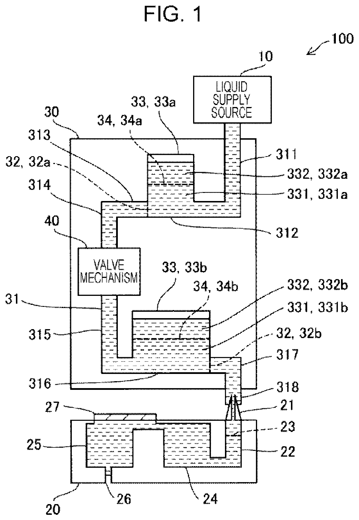
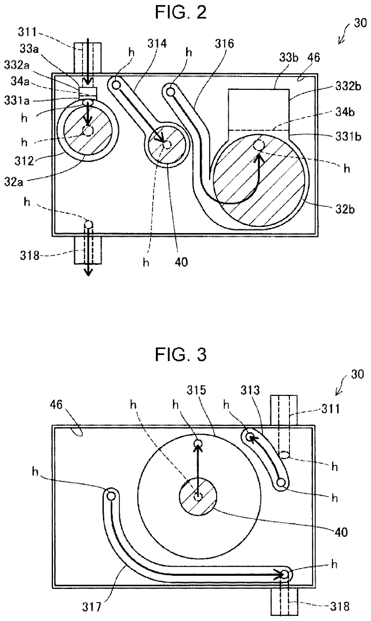
[0005](1) According to an aspect of the invention, there is provided a flow path structure body. The flow path structure body includes: a distribution flow path that is for distributing a liquid from a liquid supply source to a nozzle; an air bubble chamber that is connected to the distribution flow path and that is for storing air bubbles; an air bubble chamber filter that is arranged such that the air bubble chamber filter divides a space in the air bubble chamber into a first space that is connected to the distribution flow path and a second space that is connected to the distribution flow path via the first space, the air bubble chamber filter being for collecting foreign matters that have been formed at a gas-liquid interface in the air bubble chamber. According to the flow path structure body in the aspect, the foreign matters that have been formed at the gas-liquid interface in the air bubble chamber are collected by the air bubble chamber filter provided in the air bubble chamber. Therefore, it is possible to suppress flowing-out of the foreign matters that have been formed at the gas-liquid interface in the air bubble chamber to the distribution flow path and flowing of the foreign matters to the nozzle and to suppress nozzle clogging due to the foreign matters.
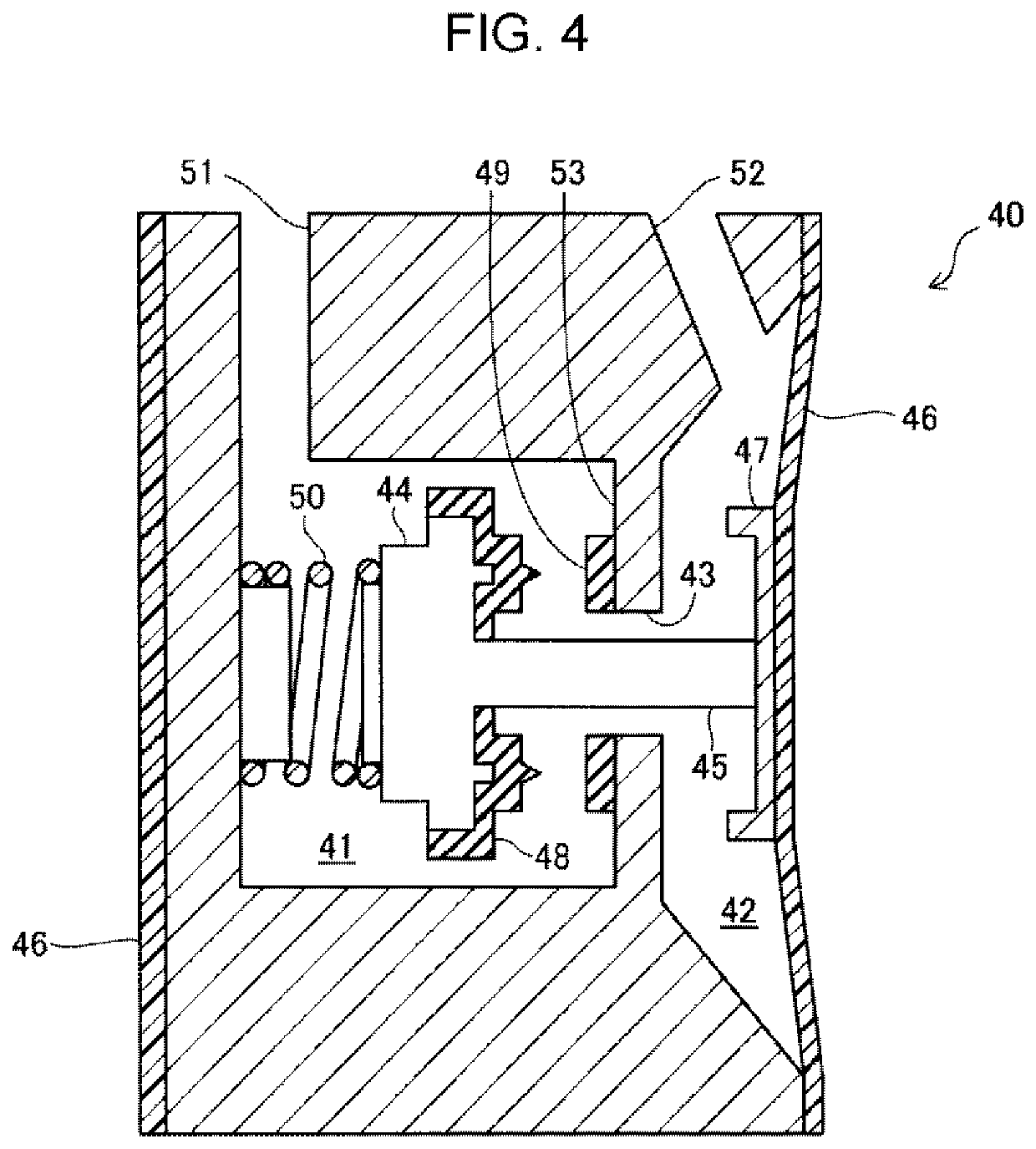
[0011](7) The flow path structure body may further include: a flow path filter that is arranged in the distribution flow path and that is for collecting foreign matters included in the liquid that flows through the distribution flow path; and a valve mechanism that is arranged on an upstream side of the flow path filter and opens and closes the distribution flow path in accordance with a pressure of the liquid on a downstream side beyond the distribution flow path, in which the air bubble chamber may be connected between the valve mechanism and the flow path filter. According to the flow path structure body in the aspect, it is possible to store the air bubbles in the air bubble chamber provided on the downstream side beyond the valve mechanism even if the air bubbles have been formed in conjunction with opening and closing operations of the valve mechanism, and it is possible to collect foreign matters with the air bubble chamber filter even if the foreign matters have been formed at the gas-liquid interface in the air bubble chamber. Therefore, it is possible to suppress flowing of the air bubbles and the foreign matters to the nozzle. In addition, it is possible to suppress a decrease in the lifetime of the flow path filter due to accumulation of the foreign matters that have been formed at the gas-liquid interface in the air bubble chamber at the flow path filter provided on the downstream side beyond the air bubble chamber.

Problems solved by technology

There is a possibility that nozzle clogging or the like occurs if the foreign matters that have been formed at the gas-liquid interface flow out to the flow path and flow to a nozzle.
Even in a case in which a filter is provided in the flow path on a downstream side beyond the air bubble chamber, there is a possibility that lifetime of the filter is degraded if the foreign matters that have been formed at the gas-liquid interface are accumulated at the filter.
According to the flow path structure body in the aspect, there is a high possibility that the air bubble chamber filter causes clogging earlier than the head filter since the roughness of the mesh of the air bubble chamber filter is finer than the roughness of the mesh of the head filter.

Method used


Image

  • Flow path structure body, liquid ejecting apparatus, and liquid ejecting method
  • Flow path structure body, liquid ejecting apparatus, and liquid ejecting method
  • Flow path structure body, liquid ejecting apparatus, and liquid ejecting method

Examples


first embodiment

A. First Embodiment

[0021]FIG. 1 is an explanatory diagram illustrating an outline of a liquid ejecting apparatus 100 according to a first embodiment. The liquid ejecting apparatus 100 according to the embodiment is configured as an ink jet printer including a liquid ejecting head 20 that has a nozzle 26 for ejecting ink (liquid) that has been supplied from a liquid supply source 10 and a flow path structure body 30 that is connected between the liquid supply source 10 and the liquid ejecting head 20 and that distributes the ink that has been supplied from the liquid supply source 10 to the liquid ejecting head 20. The flow path structure body 30 is detachably connected to the liquid ejecting head 20. The liquid ejecting head 20 and the flow path structure body 30 will be collectively referred to as a “liquid ejecting unit” in some cases.

[0022]The liquid supply source 10 is an ink supply source. The liquid supply source 10 according to the embodiment is an ink cartridge that is forme...

second embodiment

B. Second Embodiment

[0051]FIG. 6 is an explanatory diagram illustrating an outline of a liquid ejecting apparatus 100b according to a second embodiment. The liquid ejecting apparatus 100b according to the second embodiment is different from the first embodiment (FIG. 1) in the arrangement of the air bubble chamber filter 34 provided in the air bubble chamber 33. In the flow path structure body 30 according to the first embodiment as illustrated in FIG. 1, the air bubble chamber filter 34 is arranged in the horizontal direction during use when the liquid is distributed through the flow path structure body 30, and the space in the air bubble chamber 33 is divided into upper and lower portions in the vertical direction by the air bubble chamber filter 34. Meanwhile, in the flow path structure body 30b according to the embodiment, the air bubble chamber filter 34 is arranged while inclined relative to the horizontal direction as illustrated in FIG. 6 during use when the liquid is distri...

third embodiment

C. Third Embodiment

[0052]FIG. 7 is an explanatory diagram illustrating an outline of a liquid ejecting apparatus 100c according to a third embodiment. The liquid ejecting apparatus 100c according to the third embodiment is different from the first embodiment (FIG. 1) in the structure of the air bubble chamber 33. In the flow path structure body 30 according to the first embodiment as illustrated in FIG. 1, the air bubble chamber 33 is connected directly to the distribution flow path 31. Meanwhile, in the flow path structure body 30c according to the embodiment, the air bubble chamber 33 is connected to the distribution flow path 31 via a branching flow path 333 as illustrated in FIG. 7. The air bubble chamber 33 can store the air bubbles, and the foreign matters that have been formed at the gas-liquid interface can be collected with the air bubble chamber filter 34 even in the flow path structure body 30c in this mode.

D. Other Embodiments

[0053](D-1) In the air bubble chamber 33 as i...


PUM


Abstract

Provided is a flow path structure body including: a distribution flow path that is for distributing a liquid from a liquid supply source to a nozzle; an air bubble chamber that is connected to the distribution flow path and that is for storing air bubbles; and an air bubble chamber filter that is arranged to divide a space in the air bubble chamber into a first space that is connected to the distribution flow path and a second space that is connected to the distribution flow path via the first space, the air bubble chamber filter being for collecting foreign matters that have been formed at a gas-liquid interface in the air bubble chamber.

Description

BACKGROUND1. Technical Field[0001]The present invention relates to a flow path structure body, a liquid ejecting apparatus, and a liquid ejecting method.2. Related Art[0002]In relation to a flow path structure body, JP-A-2015-231722, for example, discloses a flow path member that has a filter provided at a midpoint of a flow path and an air bubble chamber for storing air bubbles removed by the filter.[0003]There is a possibility that foreign matters have been formed at a gas-liquid interface between gas and liquid that are stored in an air bubble chamber in a flow path member (flow path structure body) disclosed in JP-A-2015-231722. There is a possibility that nozzle clogging or the like occurs if the foreign matters that have been formed at the gas-liquid interface flow out to the flow path and flow to a nozzle. Even in a case in which a filter is provided in the flow path on a downstream side beyond the air bubble chamber, there is a possibility that lifetime of the filter is degr...

Claims


Application Information

Patent Timeline
Patent Type & Authority Patents(United States)
IPC IPC(8): B41J2/17B41J2/175B41J2/19
CPCB41J2/175B41J2/17513B41J2/19B41J2/17563
Inventor OTSUKI, MAKOTO
Owner SEIKO EPSON CORP
Learn More