Determination and visualization of damage to an anatomical joint

a technology for applied in the field of determining and visualizing damage to an anatomical joint of a patient, can solve problems such as the lack of manipulation functionalities of tools

Active Publication Date: 2019-04-25
EPISURF IP MANAGEMENT
View PDF0 Cites 7 Cited by
  • Summary
  • Abstract
  • Description
  • Claims
  • Application Information

AI Technical Summary

Problems solved by technology

This tool does not comprise manipulation functionalities that enable the creation of a clear visualization of anatomical structures of an anatomical joint.

Method used


Image

  • Determination and visualization of damage to an anatomical joint
  • Determination and visualization of damage to an anatomical joint
  • Determination and visualization of damage to an anatomical joint

Examples


use case embodiment

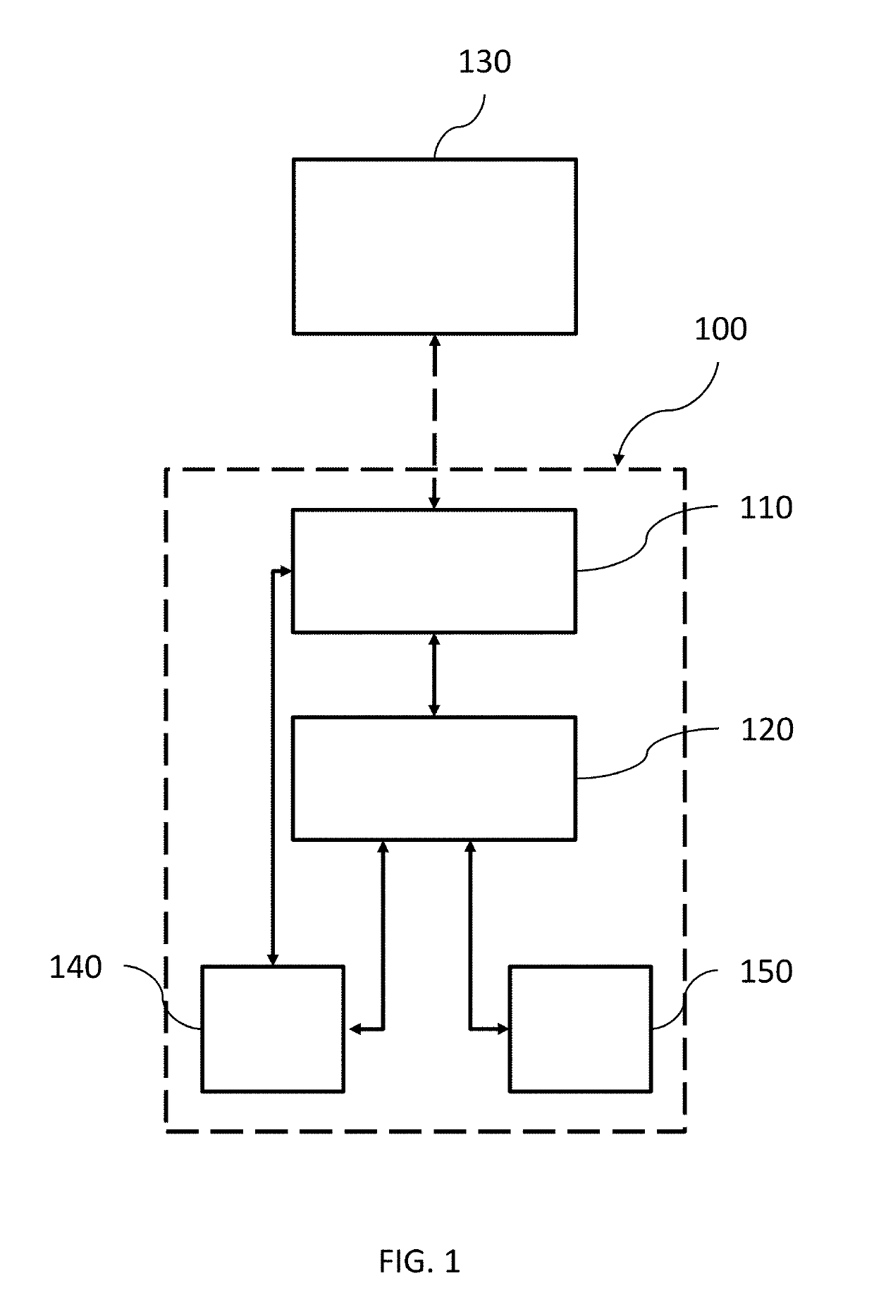
[0115]To set the presently disclosed methods and systems in a larger context, the damage marking and the creation of the graphical user interface according to any of the disclosed embodiments may in use case embodiments be preceded by capturing and / or obtaining medical image data representing an anatomical joint or part of it, and may further be followed by actions to be taken in view of repairing any determined damage.

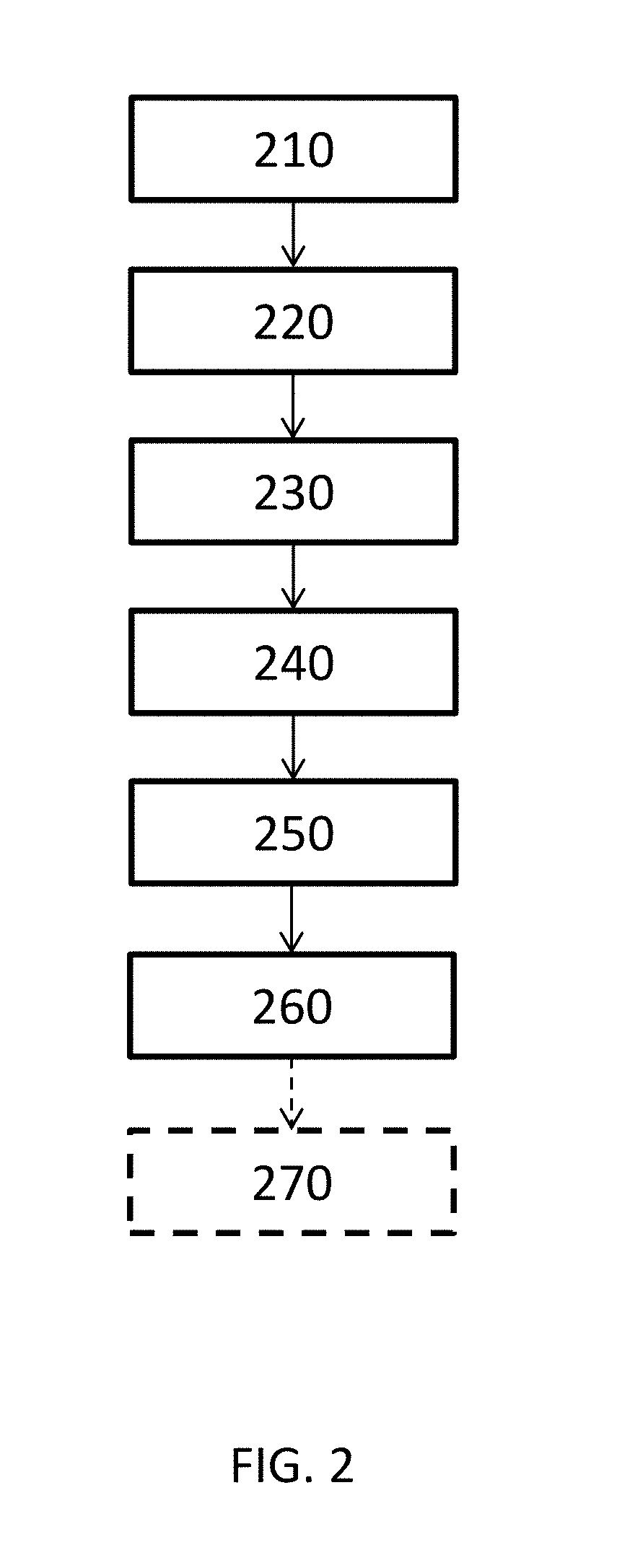
[0116]FIG. 8 is a flow diagram exemplifying one such larger context, including obtaining medical image data from an image source, determining damage to a depicted anatomical joint, and creating of a graphical user interface in accordance with one or more embodiments described herein. FIG. 8 further includes steps of designing and producing an implant and / or guide tool suitable for repairing a determined damage in an anatomical joint. In FIG. 8, everything except the determination of damage, damage marking and graphical user interface creation of step 840, using the in...


PUM


Abstract

In accordance with one or more embodiments herein, a system for determining and visualizing damage to an anatomical joint of a patient is provided. The system comprises a display, at least one manipulation tool, a storage media and at least one processor. The at least one processor is configured to: i) receive a plurality of medical image stacks of at least a part of the anatomical joint from the storage media; ii) obtain a three-dimensional image representation of the at least part of the anatomical joint which is based on at least one of said medical image stacks, by generating said three-dimensional image representation in an image segmentation process based on said medical image stack, or receiving said three-dimensional image representation from the storage media; iii) determine damage to at least one of a plurality of anatomical structures in the anatomical joint by analyzing at least one of said plurality of medical image stacks; iv) mark, based on the determined damage, damage to the anatomical structures in the obtained three-dimensional image representation; v) obtain at least one 3D model for visualization based on the three-dimensional image representation, in which 3D model the marked damage is visualized; and vi) create a graphical user interface for visualization on the display. The graphical user interface may comprise: functionality to visualize and enable manipulation, using the at least one manipulation tool, of the at least one 3D model; functionality to enable removal of the visualization of at least one of the plurality of anatomical structures from the at least one 3D model; functionality to visualize and enable browsing of at least one of the plurality of medical image stacks; and functionality to, in the 3D model, visualize the position of the at least one medical image that is currently visualized.

Description

CROSS-REFERENCE TO RELATED APPLICATIONS[0001]This application is a continuation-in-part of U.S. application Ser. No. 16 / 010,344, filed Jun. 15, 2018, entitled “CREATION OF A DECISION SUPPORT MATERIAL INDICATING DAMAGE TO AN ANATOMICAL JOINT,” which is a continuation-in-part of U.S. application Ser. No. 15 / 625,873, filed Jun. 16, 2017, entitled “SYSTEM AND METHOD FOR CREATING A DECISION SUPPORT MATERIAL INDICATING DAMAGE TO AN ANATOMICAL JOINT” and further incorporates by reference for all purposes the full disclosure of PCT Application No. ______, filed concurrently herewith, entitled “CREATION OF A DECISION SUPPORT MATERIAL INDICATING DAMAGE TO AN ANATOMICAL JOINT” (Attorney Docket No. 0107246-002WO0), and co-pending U.S. patent application Ser. No. 15 / 611,685, filed Jun. 1, 2017, entitled “SYSTEM AND METHOD FOR CREATING A DECISION SUPPORT MATERIAL INDICATING DAMAGE TO AN ANATOMICAL JOINT,” which is a continuation of U.S. patent application Ser. No. 15 / 382,523, filed Dec. 16, 2016,...

Claims


Application Information

Patent Timeline
Patent Type & Authority Applications(United States)
IPC IPC(8): G06T7/00A61B6/00A61B34/10G06T15/00
CPCG06T7/0012A61B6/466A61B34/10G06T15/00A61B2034/105A61B2034/108G06T2207/30008A61B2034/107A61B6/032A61B6/50A61B6/5217G06T17/00G06T19/20G06T2219/028G06T2207/10081G16H50/30
Inventor LILLIESTR LE, RICHARDKARLSSON, ANDERSSP NGBERG, JEANETTEBAKE, NINABRATT, INGRID
Owner EPISURF IP MANAGEMENT
Why Eureka
Try Eureka