System Level Health Monitoring in Test Systems

a health monitoring and system level technology, applied in continuity testing, short-circuit testing, instruments, etc., can solve problems such as poor first pass yield, automatic test failure, and wearout of these cables

Active Publication Date: 2019-05-09
NATIONAL INSTRUMENTS
View PDF0 Cites 2 Cited by
  • Summary
  • Abstract
  • Description
  • Claims
  • Application Information

AI Technical Summary

Benefits of technology

[0010]In some embodiments, an instrument in an automated test system may have the ability to measure connected cables between the input of the instrument and a device under test coupled to the instrument, to help identify when the input has undergone enough wear to prompt maintenance, to prevent actual failure and production downtime caused by interconnectivity equipment failure, or more generally by equipment failure. In some embodiments the instrument may include a processing unit executing program instructions (i.e. software; SW), a data acquisition (DAQ) hardware device for acquiring sample data and/or gen

Problems solved by technology

One of the major sources of automated test failure is the wearing out of these cables, connectors, relays, etc.
The failure of such components can lead to poor first pass yields, increased tota

Method used


Image

  • System Level Health Monitoring in Test Systems
  • System Level Health Monitoring in Test Systems
  • System Level Health Monitoring in Test Systems

Examples


Embodiment Construction

[0023]Embodiments of the present invention may be used in systems configured to perform test and / or measurement functions, to control and / or model instrumentation or industrial automation hardware, or to model and simulate functions, e.g., modeling or simulating a device or product being developed or tested, etc. However, it is noted that the present invention may equally be used for a variety of applications, and is not limited to the applications enumerated above. In other words, applications discussed in the present description are exemplary only, and the present invention may be used in any of various types of systems. Thus, the system and method of the present invention is operable to be used in any of various types of applications, including the control of other types of devices such as multimedia devices, video devices, audio devices, telephony devices, Internet devices, etc.

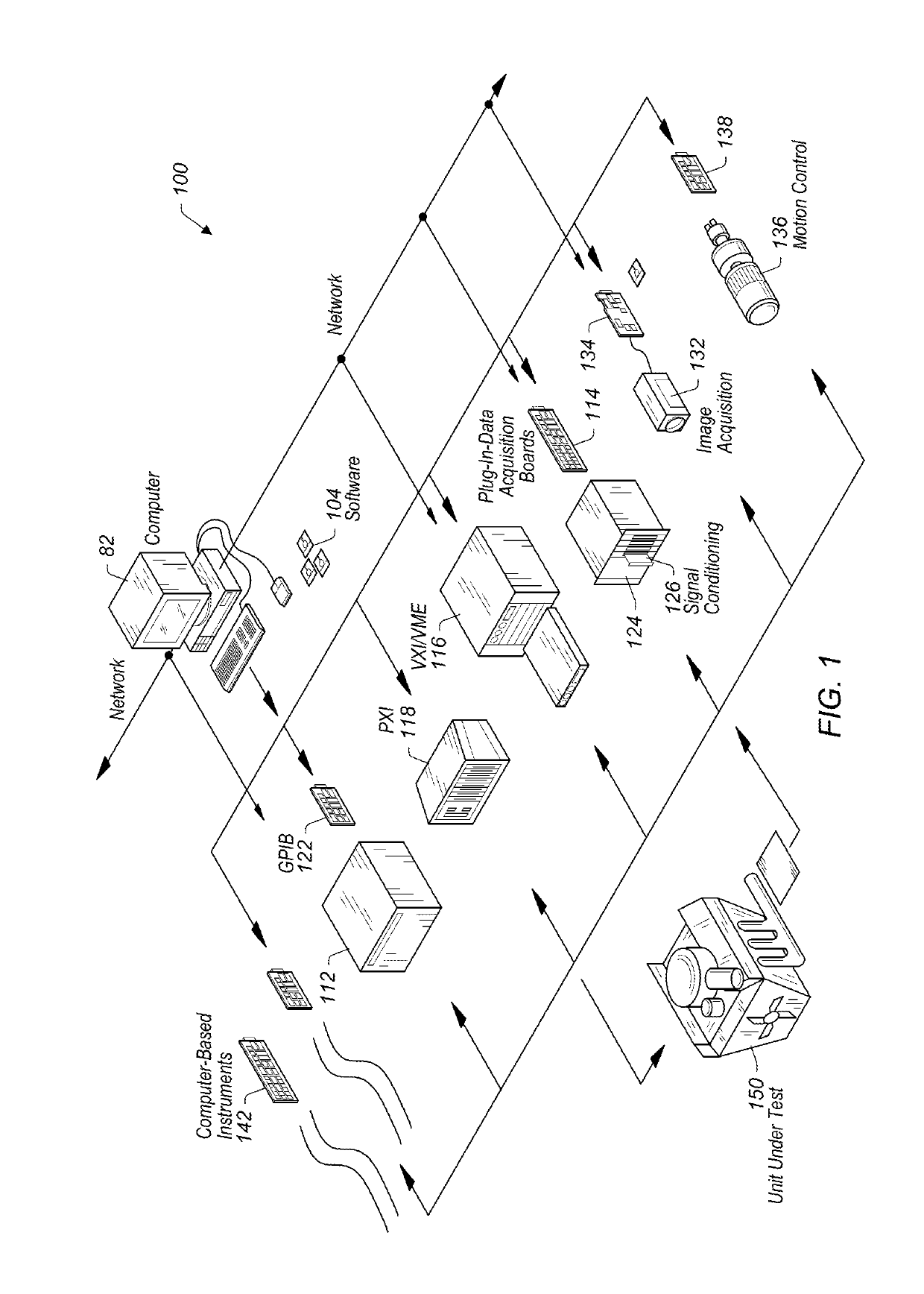
[0024]FIG. 1 illustrates an exemplary instrumentation control system 100 which may be configured accor...


PUM


Abstract

To perform system level physical connectivity monitoring measurements, a test signal may be generated in an instrument and transmitted down a signal path extending from the instrument to a device. In a static state (high or low), the test signal generator may produce a specified AC impedance at the point where the signal path connects to the instrument for a designated back termination. A response signal resulting from the test signal may be acquired and used to obtain an impedance value and/or reflection coefficient value representative of the signal path and an additional signal path extending from the source of the test signal to the signal path. The measured response may be compared to an expected response to determine a condition of any component(s) in the signal path and/or in the additional signal path. The expected response may be represented by masks (low and high) created during automated test development.

Description

PRIORITY CLAIM[0001]This application claims benefit of priority of U.S. Provisional Patent Application Ser. No. 62 / 582,031 titled “System Level Health Monitoring in Test Systems”, filed on Nov. 6, 2017, which is hereby incorporated by reference as though fully and completely set forth herein.BACKGROUND OF THE INVENTIONField of the Invention[0002]This invention relates generally to measurement and data acquisition systems and, more particularly, to improving system level health monitoring in test systems.Description of the Related Art[0003]Measurement systems are oftentimes used to perform a variety of functions, including measurement of physical phenomena, measurement of certain characteristics or operating parameters of a unit under test (UUT) or device under test (DUT), testing and analysis of physical phenomena, process monitoring and control, control of mechanical or electrical machinery, data logging, laboratory research, and analytical chemistry, to name a few examples.[0004]A...

Claims


Application Information

Patent Timeline
IPC IPC(8): G01R31/28
CPCG01R31/2834G01R31/52G01R31/54G01R31/58G01R31/68
Inventor ORMSTON, JESSE D.
Owner NATIONAL INSTRUMENTS
Why Eureka
Try Eureka