
Biocompatible implantable sensor apparatus and methods

a sensor and biocompatible technology, applied in the field of biocompatible implantable sensor apparatus and methods, can solve the problems of not being able to realistically expect, preclude warning strategies, and not being able to meet the needs of patients, and achieve the effects of enhancing or enabling the performance of sporting activities, reducing the size of the body, and less functionality

Inactive Publication Date: 2019-05-23
GLYSENS
View PDF0 Cites 4 Cited by
  • Summary
  • Abstract
  • Description
  • Claims
  • Application Information

AI Technical Summary

Benefits of technology

[0032]In another variant, the wireless signals encoding data are scrambled according to a unique scrambling code prior to transmission from the device, and the apparatus is further configured to unscramble the received wireless signals based at least in part on the unique scrambling code. The wireless signals are transmitted from the device e.g., only at prescribed times or prescribed intervals, and the apparatus is configured to enable the wireless receiver apparatus to receive the wireless signals only during the prescribed times or at the prescribed intervals, and otherwise maintain at least a portion of the wireless receiver apparatus in a dormant or sleep state so as to conserve electrical power of the electrical power source.
[0050]In another aspect of the disclosure, a method of monitoring blood glucose level while engaging in a sporting activity is disclosed. In one embodiment, the method includes wearing a limited functionality and limited form-factor local wireless receiver apparatus to: (i) receive data wirelessly transmitted from an implanted blood glucose sensor; (ii) process the received data to generate at least an estimated blood glucose level; and (iii) provide indication of the estimated blood glucose level to the user during the sporting activity. In one variant, the limited form factor is enabled at least in part by the limited functionality (i.e., less functionality equates to smaller form factor), and the limited form factor enhances or enables performance of the sporting activity (e.g., reduces overall wearer weight, hydrodynamic friction, bulk, etc.).

Problems solved by technology

This procedure has several disadvantages, including: (1) the discomfort associated with the procedure, which should be performed repeatedly each day; (2) the near impossibility of sufficiently frequent sampling (some blood glucose excursions require sampling every 20 minutes, or more frequently, to accurately treat); and (3) the requirement that the user initiate blood collection, which precludes warning strategies that rely on automatic early detection.
Using the extant fingersticking procedure, the frequent sampling regimen that would be most medically beneficial cannot be realistically expected of even the most committed patients, and automatic sampling, which would be especially useful during periods of sleep, is not available.
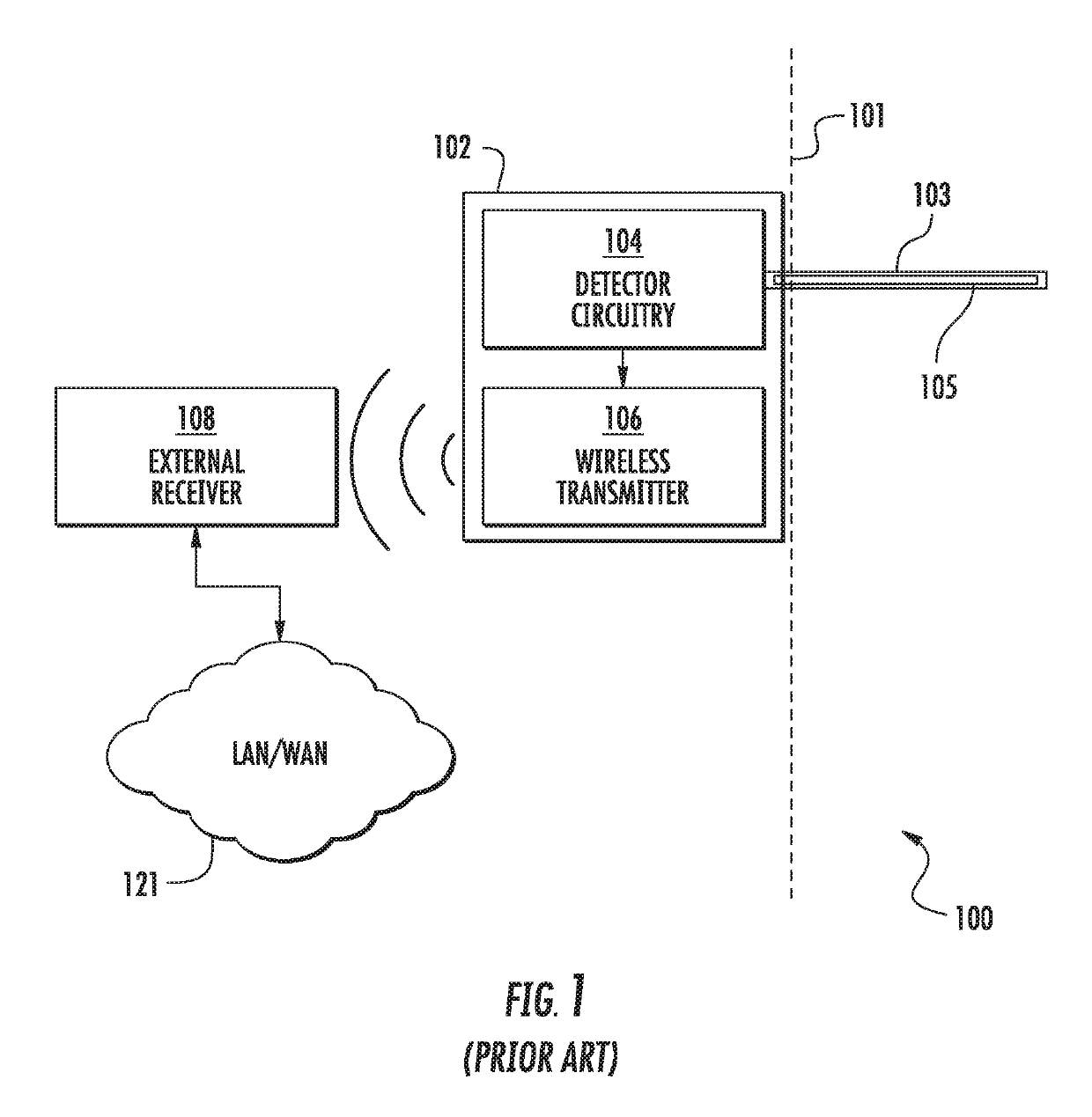
While the maximum wireless range of the exemplary G5 device is generally commensurate with that of other Bluetooth-enabled devices (e.g., typically on the order of 30 feet or so), and hence gives some degree of flexibility to receiver placement relative to the user (and the sensor device 102), there are significant disabilities with this scheme, including notably the inability for the user to engage in some activities which require dissociation of the user (and device 102) from the receiver due to distance, an intervening and interfering medium such as water, etc., or incompatibility of the receiver with such media.
Moreover, such receivers can add significant weight and / or bulk to the user when affixed thereto, thereby potentially reducing their competitiveness in high-end sporting activities such as marathons, gymnastics, triathlons, bicycle racing, etc.
Hence, in essence, a user of such prior art systems must have their receiver (dedicated or smartphone) with them at all times, and the system is unforgiving for transgressions of this requirement.
Potential failure of such equipment (whether due to equipment failure, loss of battery charge, etc.) also requires some degree of “planning ahead” for the user including e.g., making sure that their receiver or smartphone is charged sufficiently, and / or a backup exists in case their receiver / smartphone is damaged or otherwise disabled.

Method used


Image

  • Biocompatible implantable sensor apparatus and methods
  • Biocompatible implantable sensor apparatus and methods
  • Biocompatible implantable sensor apparatus and methods

Examples


Embodiment Construction

[0083]Reference is now made to the drawings, wherein like numerals refer to like parts throughout.

Overview

[0084]One aspect of the present disclosure leverages Assignee's recognition that many of the above-described disabilities of the prior art “receiver” approach (including the user being effectively tethered to their analyte monitoring system receiver) can be mitigated or even completely eliminated.

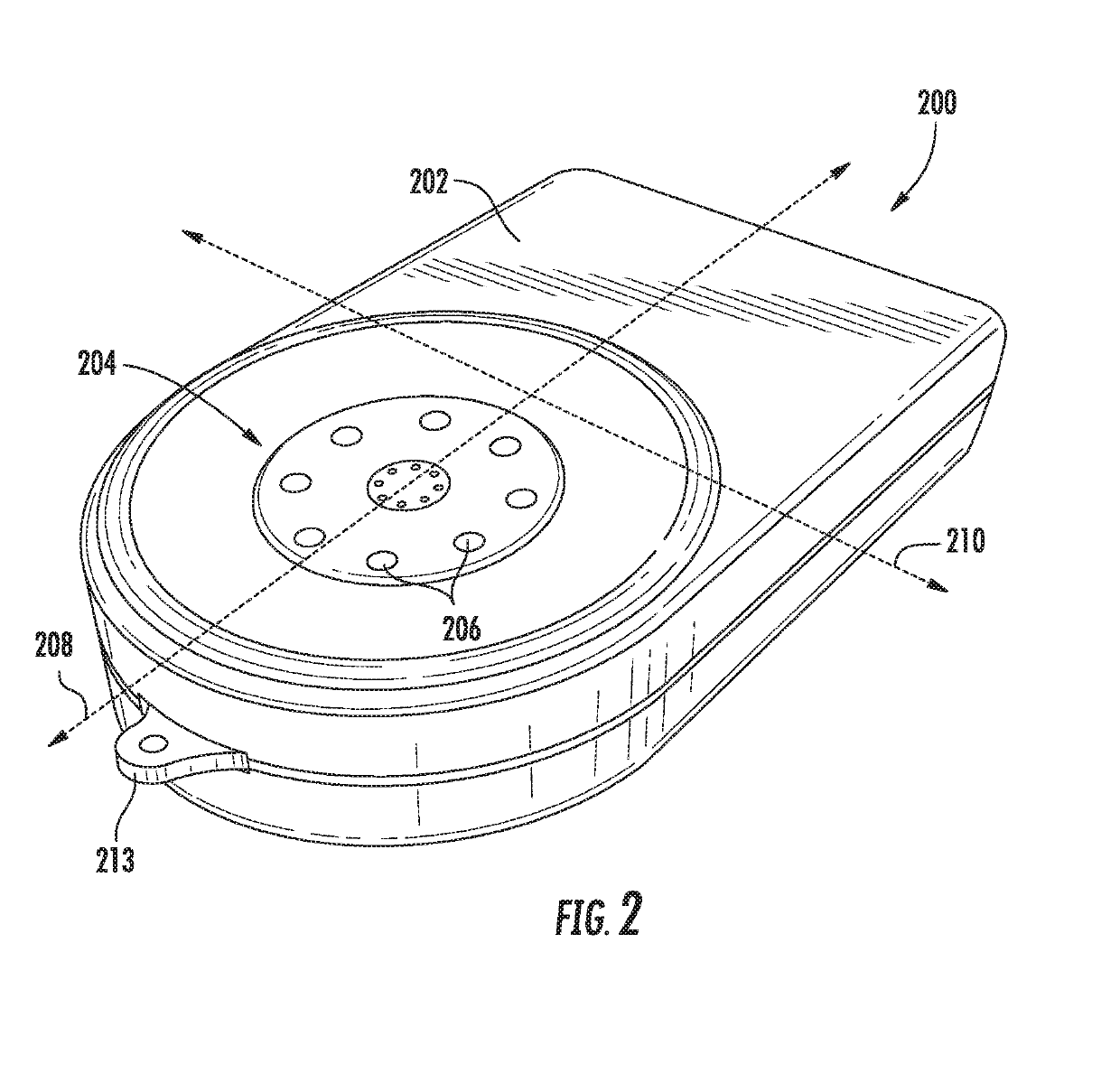
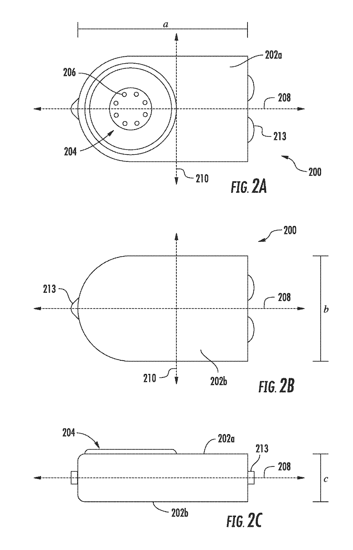
[0085]Accordingly, the present disclosure makes use in one exemplary embodiment of a minimal profile (and functionality) receiving device which the user can discretely carry or wear continuously, so as to obviate the bulky and more full-featured receiver(s) of the prior art. In this fashion, the user is largely freed from concerns such as forgetting their receiver / smartphone, having it maintained in a constant state of charge, and notably refraining from activities which would otherwise be impossible or at least highly impractical under the prior art (e.g., watersports including swimmin...


PUM


Abstract

Receiver apparatus for use with an analyte sensor, and methods of operation and manufacturing. In one embodiment, the analyte sensor is an implanted / implantable blood glucose sensor, including oxygen-based detector elements. The receiver apparatus is a wireless-enabled small form-factor device with limited functionality that can be easily worn or kept with the user on a continual basis, thereby obviating the need for a more fully featured receiver or smartphone for extended periods of time (e.g., one week). The exemplary oxygen based analyte sensor, with high degree of stability over time, enables the user to divorce themselves from the more fully functioned receiver or smartphone, since no external calibration of the sensor is required during the extended period. In one variant, the device is a lightweight wristband. Other variants include e.g., pendants, finger-worn rings, arm or head bands, skin patches, and even dental, subcutaneous, or prosthetic implants.

Description

RELATED APPLICATIONS[0001]This application is related to co-owned and co-pending U.S. patent application Ser. No. 13 / 559,475 filed Jul. 26, 2012 entitled “Tissue Implantable Sensor With Hermetically Sealed Housing,” U.S. patent Ser. No. 14 / 982,346 filed Dec. 29, 2015 and entitled “Implantable Sensor Apparatus and Methods”, Ser. No. 15 / 170,571 filed Jun. 1, 2016 and entitled “Biocompatible Implantable Sensor Apparatus And Methods”, Ser. No. 15 / 197,104 filed Jun. 29, 2016 and entitled “Bio-adaptable Implantable Sensor Apparatus And Methods”, and Ser. No. 15 / 359,406 filed Nov. 22, 2016 and entitled “Heterogeneous Analyte Sensor Apparatus and Methods”, each of the foregoing incorporated herein by reference in its entirety. This application is also related to U.S. patent application Ser. No. 10 / 719,541 filed Nov. 20, 2003, now issued as U.S. Pat. No. 7,336,984 and entitled “Membrane and Electrode Structure for Implantable Sensor,” also incorporated herein by reference in its entirety.COP...

Claims


Application Information

Patent Timeline
Patent Type & Authority Applications(United States)
IPC IPC(8): A61B5/145A61B5/00A61B5/1495A61B5/07
CPCA61B5/14503A61B5/6833A61B5/14532A61B5/14542A61B5/1495A61B5/7445A61B5/076A61B5/6861A61B5/741A61B5/7415A61B5/682A61B2560/0219A61B2560/0223A61B5/0002A61B5/0031A61B5/1459A61B5/1486A61B5/14865A61B5/4839A61B5/681
Inventor ROUTH, TIMOTHYLUCISANO, JOSEPHMARKLE, WILLIAMPERKINS, MICHAEL
Owner GLYSENS
Learn More