
Device connector

Active Publication Date: 2019-05-23
SUMITOMO WIRING SYST LTD
View PDF0 Cites 1 Cited by
  • Summary
  • Abstract
  • Description
  • Claims
  • Application Information

AI Technical Summary

Benefits of technology

The patent text describes a connector configuration that prevents accidental engagement with the fixing bolt, thus inhibiting erroneous operations. The technical effects of this configuration include a bulged portion on the cover member that makes it difficult to engage a tool with the fixing bolt and a lock portion on the fastening member that makes it difficult to engage a tool with the fixing bolt. Additionally, using the end portion of the belt-shaped portion of the fastening member makes it more difficult to engage a tool with the fixing bolt. This configuration allows for safer and more reliable connections without the need for additional members.

Problems solved by technology

However, when removing the wire-side connector from a device connector such as the one described above, an erroneous operation such as erroneously removing the device-side connector before removing the wire-side connector earlier may be performed.
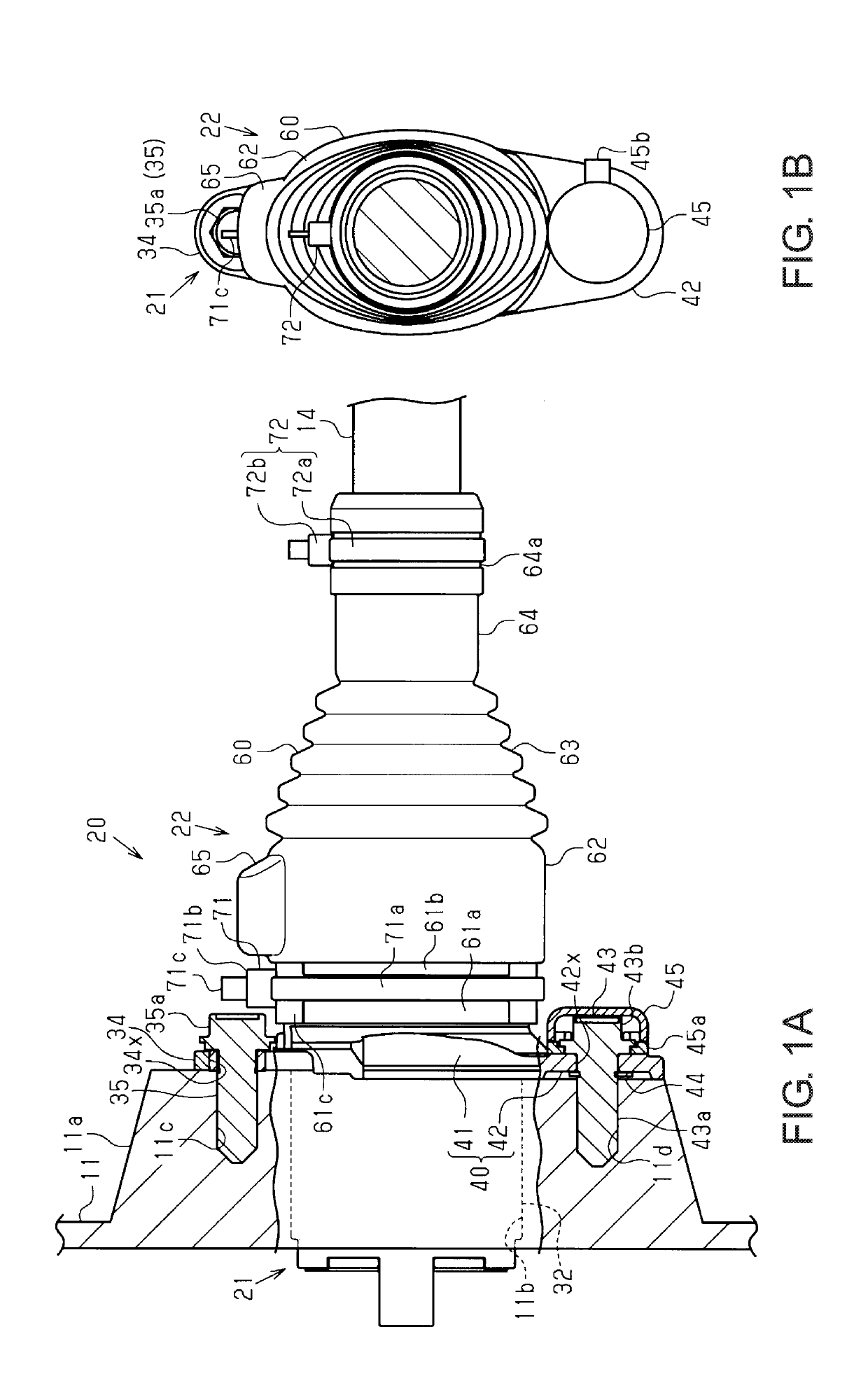
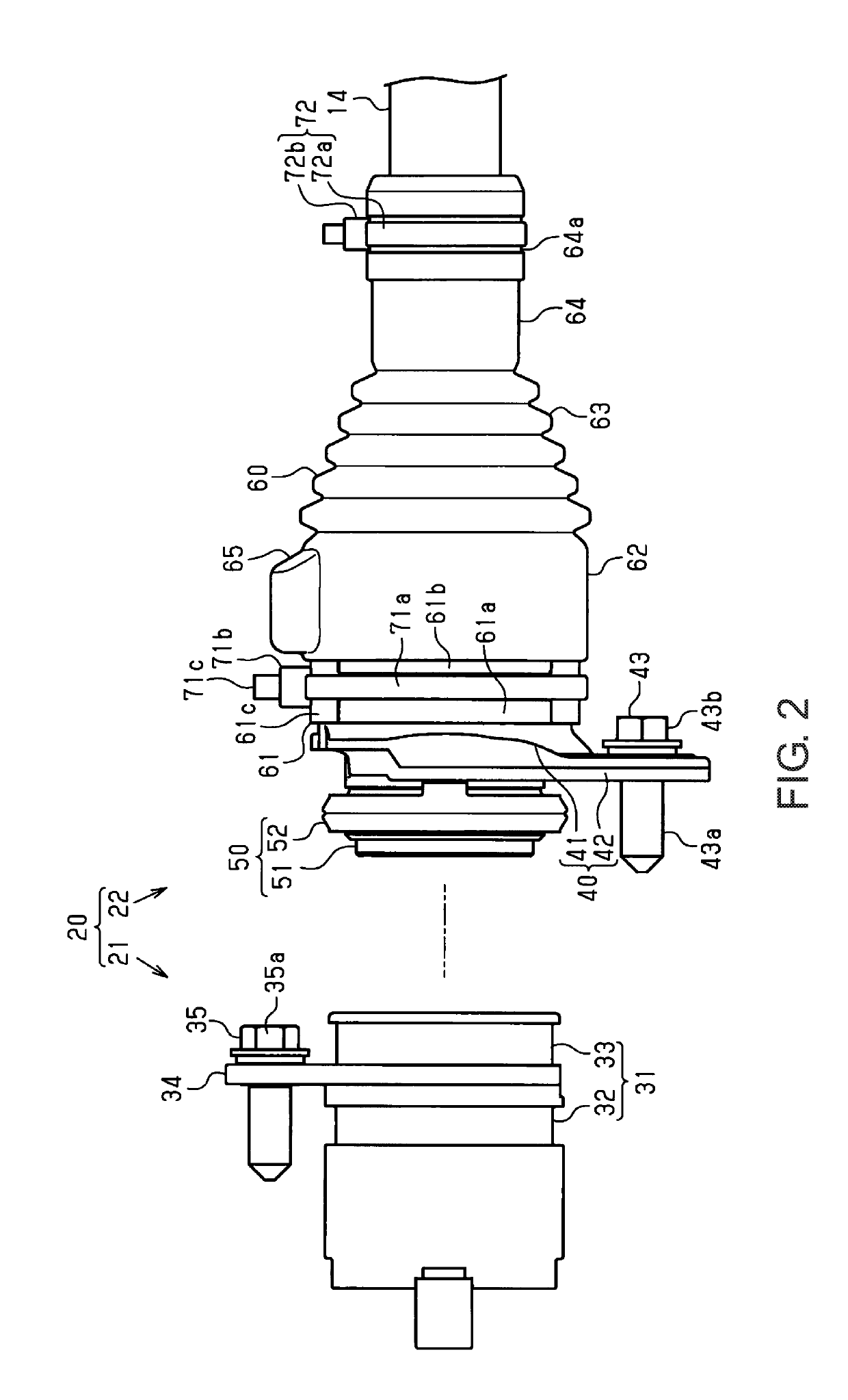
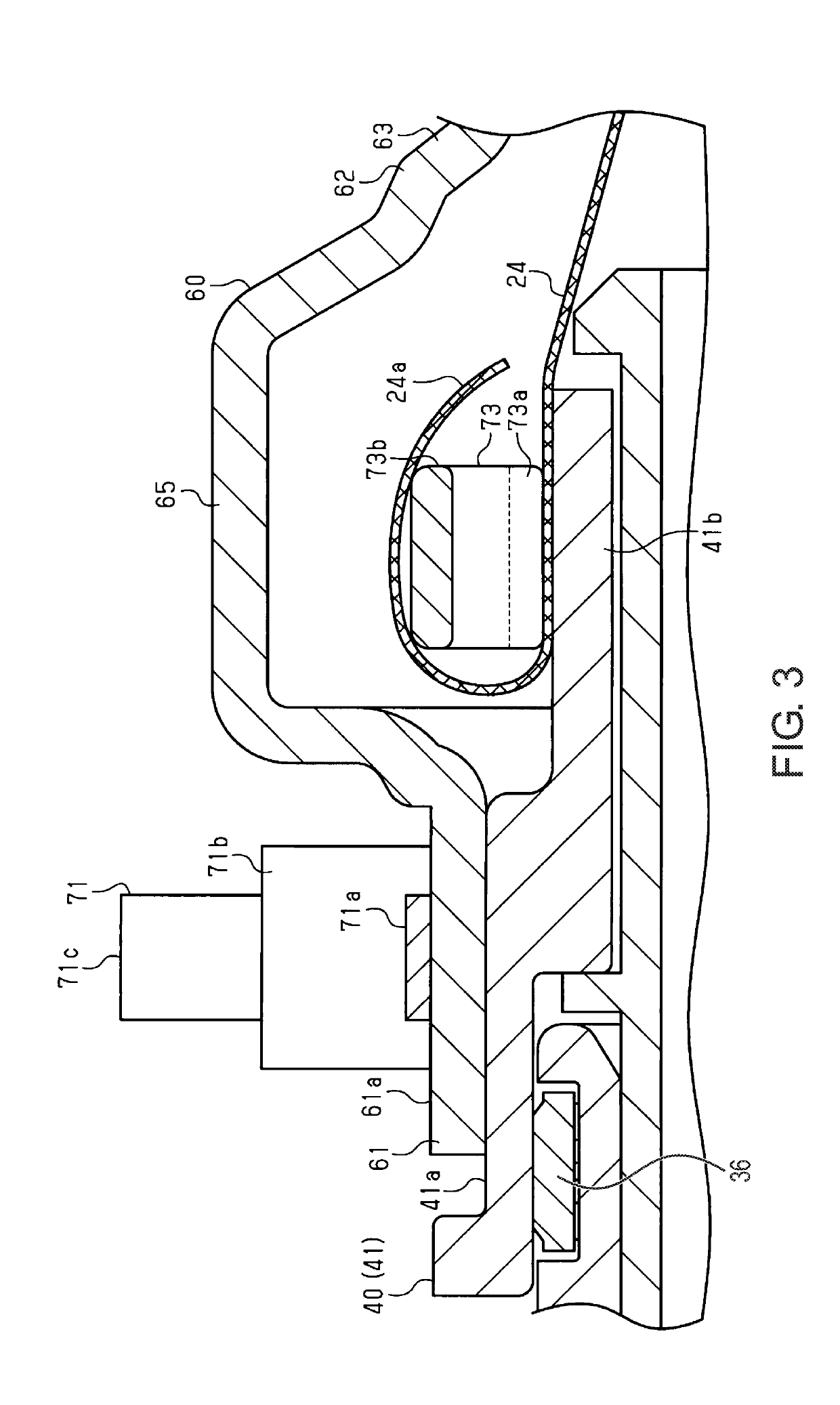
The bulged portion makes it difficult to engage a tool with the fixing bolt, thus inhibiting the removal of the fixing bolt.
With this configuration, the bulged portion and the fastening member of the cover member make it further difficult to engage a tool with the fixing bolt, thus making it possible to inhibit erroneous operations.
With this configuration, the lock portion of the fastening member makes it difficult to engage a tool with the fixing bolt.
With this configuration, using the end portion of the belt-shaped portion of the fastening member makes it more difficult to engage a tool with the fixing bolt, thus making it possible to inhibit erroneous operations.

Method used


Image

  • Device connector
  • Device connector
  • Device connector

Examples


Embodiment Construction

[0025]Hereinafter, embodiments will be described.

[0026]Note that the accompanying drawings may show enlarged constituent elements in order to facilitate understanding. The dimensional proportions of the constituent elements may be different from the actual proportions, or the proportions shown in the drawings. In the cross-sectional views, the hatching for some of the constituent elements may be omitted in order to facilitate understanding.

[0027]A vehicle 10 shown in FIG. 5 is a hybrid car, an electric car, or the like, for example. The vehicle 10 includes an inverter 11 as a device, a high-voltage battery 12, and a wire harness 13 that electrically connects the inverter 11 and the high-voltage battery 12 to each other. The inverter 11 is mounted in the front portion of the vehicle 10, and the high-voltage battery 12 is mounted in the rear portion of the vehicle 10. The wire harness 13 is routed so as to pass underneath the floor of the vehicle 10.

[0028]The wire harness 13 includes ...


PUM


Abstract

Erroneous operations are to be inhibited. A device connector includes a device-side connector and a wire-side connector. The device-side connector is fixed to a case by a fixing bolt that is threaded to a bolt fixing hole provided in the case. The wire-side connector is fixed to the case by a fastening bolt, and is connected to the device-side connector. The wire-side connector includes a connector shell that has an insertion hole through which the fastening bolt is to be passed, and a cover member configured to be attached to cover the connector shell. The cover member includes a housing portion disposed on the axis of the fixing bolt.

Description

TECHNICAL FIELD[0001]The present disclosure relates to a device connector.BACKGROUND ART[0002]Conventionally, a device connector that is fixed to an electric device mounted on a vehicle, such as an inverter, by a fastening bolt has been proposed. The device connector includes a wire-side connector connected to an end of a wire, and a device-side connector capable of being fitted to the wire-side connector, and these connectors are each fixed to a case of the electric device by a bolt (e.g., see JP 2012-128966M.[0003]JP 2012-128966A is an example of related art.SUMMARY[0004]However, when removing the wire-side connector from a device connector such as the one described above, an erroneous operation such as erroneously removing the device-side connector before removing the wire-side connector earlier may be performed.[0005]It is an object of certain preferred embodiments to provide a device connector capable of inhibiting erroneous operations.[0006]A device connector that solves the a...

Claims


Application Information

Patent Timeline
IPC IPC(8): H01R13/621H01R13/639H01R13/52B60R16/02
CPCH01R13/6215H01R13/639H01R13/5221B60R16/0215H01R2201/26H01R13/516H01R13/5219H01R13/621H01R13/64H01R13/6592H01R13/748
Inventor FUJIKI, MASASHI
Owner SUMITOMO WIRING SYST LTD
Learn More