
Pet waste collection apparatus

Inactive Publication Date: 2006-08-29
SMELTZER MICHAEL
View PDF16 Cites 29 Cited by
  • Summary
  • Abstract
  • Description
  • Claims
  • Application Information

AI Technical Summary

Benefits of technology

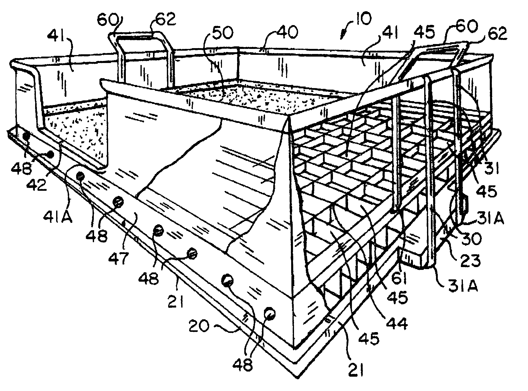
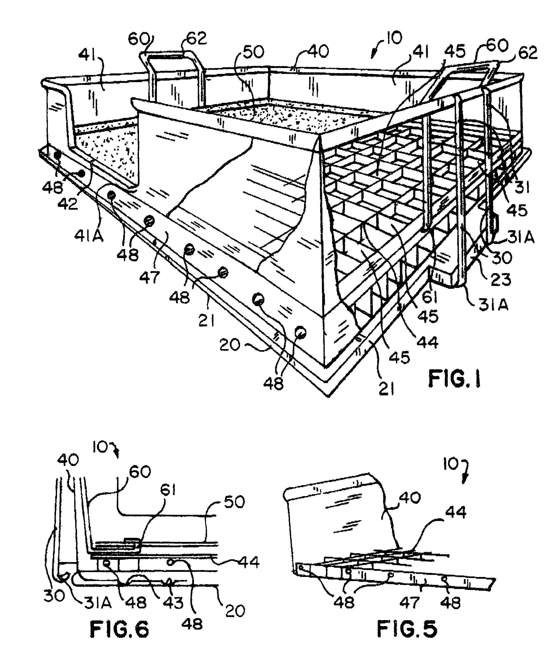
[0014]A housing is removably mounted on top of the basin and is sized and shaped for being intermediately situated along the axis. Such a housing includes a plurality of integral and opaque sidewalls protruding upwardly from the basin and terminating vertically thereabove at a predetermined height. One of the sidewalls has a passageway formed therein for allowing a pet to conveniently access the apparatus as desired. The housing preferably has a lower perimeter portion provided with a plurality of selectively spaced ribs angled downwardly from the sidewalls. Such ribs are in fluid communication with the partitions for effectively directing fluid feces into the basin.
[0015]The housing also includes a mesh-like bottom layer, preferably coated with a non-corrosive material, defining a plurality of symmetrically oriented partitions for effectively allowing fluid feces to pass downwardly therethrough and into the basin. This isolates and maintains the solid feces thereabove so that a user can readily dispose of the solid feces without separating the basin from the housing. Such partitions have generally rectangular shapes. The bottom layer preferably has opposed end corners defining a plurality of passageways for effectively channeling fluid feces distally from the axis.

Problems solved by technology

With the enactment of laws in many locations requiring owners to remove from the streets and sidewalks solid wastes left by pets, the amount of distasteful work involved in keeping pets has increased.
In some cases, the prior art is not connected to the home's conventional plumbing system and this can cause the need for human intervention in order to properly clean the device.
In other cases, the device's structure is such that it limits the size of the pet, so that only smaller animals can use the device.
In still other prior art toilets, a timing device could cause the toilet to flush while in use or a malfunction of moveable flooring, upon flushing, could injure the pet.

Method used


Image

  • Pet waste collection apparatus
  • Pet waste collection apparatus
  • Pet waste collection apparatus

Examples


Embodiment Construction

[0026]The present invention will now be described more fully hereinafter with reference to the accompanying drawings, in which a preferred embodiment of the invention is shown. This invention may, however, be embodied in many different forms and should not be construed as limited to the embodiment set forth herein. Rather, this embodiment is provided so that this application will be thorough and complete, and will fully convey the true scope of the invention to those skilled in the art. Like numbers refer to like elements throughout the figures.

[0027]The apparatus of this invention is referred to generally in FIGS. 1–4 by the reference numeral 10 and is intended to provide a pet waste collection apparatus. It should be understood that the apparatus 10 may be used to collect many different types of pet wastes and should not be limited to only cats.

[0028]Referring initially to FIG. 1, the apparatus 10 includes a basin 20 having a centrally disposed longitudinal axis and oppositely spa...


PUM


Abstract

A portable apparatus for collecting pet feces includes a basin having oppositely spaced edge portions, a planar bottom surface and a pair of oppositely disposed flange portions protruding outwardly. A housing is mounted on top of the basin and includes integral and opaque sidewalls protruding upwardly from the basin. One sidewall has a passageway formed therein. The housing further includes a grass-like top layer positionable on a mesh-like bottom layer. The apparatus further includes wire handles having lower end portions positionable below the top layer and engageable therewith and top end portions protruding upwardly from the sidewalls. The sidewalls allow a user to maintain a substantially stable grip of the top layer when removing the solid feces during non-operating conditions. The handle lower end portions have generally L-shapes for traversing upwardly and rearwardly through the bottom layer.

Description

CROSS REFERENCE TO RELATED APPLICATIONS[0001]Not Applicable.STATEMENT REGARDING FEDERALLY SPONSORED RESEARCH OR DEVELOPMENT[0002]Not Applicable.REFERENCE TO A MICROFICHE APPENDIX[0003]Not Applicable.BACKGROUND OF THE INVENTION[0004]1. Technical Field[0005]This invention relates to a waste collection apparatus and, more particularly, to a pet waste collection apparatus for collecting pet feces.[0006]2. Prior Art[0007]With the enactment of laws in many locations requiring owners to remove from the streets and sidewalks solid wastes left by pets, the amount of distasteful work involved in keeping pets has increased. Thus, there is a well recognized need for accommodating pets, especially dogs, to defecate. This is true not only in large cities but also in smaller ones as well.[0008]It is known that there are some pet toilets in which entry of the pet onto an upwardly biased treadle forces the treadle to a level position which, in turn, conditions a valve actuation arrangement for openi...

Claims


Application Information

Patent Timeline
IPC IPC(8): A01K29/00
CPCA01K1/0114
Inventor SMELTZER, MICHAEL
Owner SMELTZER MICHAEL
Learn More