Inverse rendering of visual material properties

a technology of visual material and properties, applied in the field of inverse rendering of visual material properties, can solve the problems of difficult to assess visual material properties, lack of realism of 3d models, and difficulty in assessing visual material properties

Active Publication Date: 2019-05-30
LOWES CO INC
View PDF2 Cites 35 Cited by
  • Summary
  • Abstract
  • Description
  • Claims
  • Application Information

AI Technical Summary

Benefits of technology

[0009]Another embodiment of the disclosure is directed to a 3D imaging system comprising one or more camera devices, a processor, and a memory including instructions that, when executed with the processor, cause the system to, at least: generate a virtual light source that approximates a light source, receive one or more captured images of an object with the light source, receive user information regarding one or more operational constraints, generate a grid of virtual images, using the generated virtual light source, with each virtual image having a specified visual material property value according to a position within the grid, compare at least one virtual image in the grid to the one or more captured images, calculate, based on the comparison between each virtual image in the grid and the one or more captured images, an image error, identify a virtual image of the grid of virtual images associated with a minimum image error, and assign at least one visual material property value associated with the identified virtual image to the first

Problems solved by technology

However, due to lighting and reflectiveness of a sample being scanned, some visual material properties, such as whether an item is metallic or has rough surfaces, can be hard to assess.
For example, it is often difficult to assess visual material properti

Method used


Image

  • Inverse rendering of visual material properties
  • Inverse rendering of visual material properties
  • Inverse rendering of visual material properties

Examples


Embodiment Construction

[0021]In the following description, various embodiments will be described. For purposes of explanation, specific configurations and details are set forth in order to provide a thorough understanding of the embodiments. However, it will also be apparent to one skilled in the art that the embodiments may be practiced without the specific details. Furthermore, well-known features may be omitted or simplified in order not to obscure the embodiment being described.

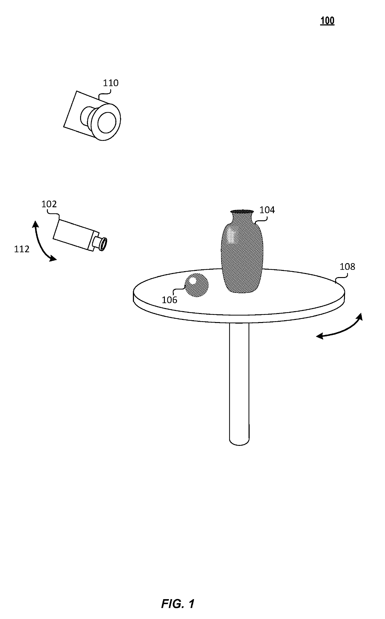
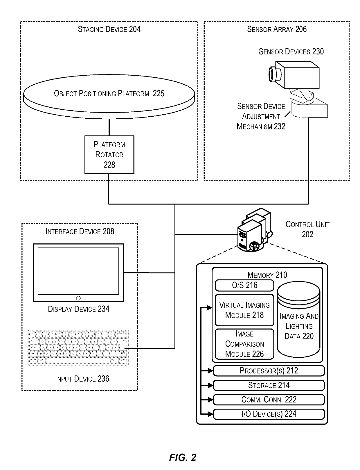
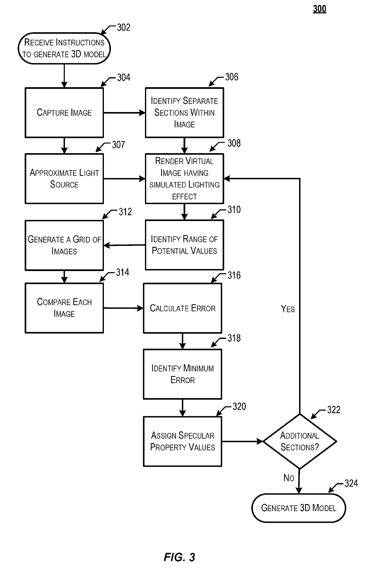
[0022]Techniques described herein are directed to a three-dimensional (3D) imaging system configured to generate a 3D model of an object using inverse rendering of material properties. The imaging system may iterate through a number of sections of an object when generating a 3D model of the object. In some embodiments, a range of material properties may be pre-defined and stored in the imaging system. Once an appropriate range of material properties is selected, the generation of the 3D model may occur in accordance with this r...


PUM


Abstract

Techniques described herein are directed to a system and methods for generating 3D models of an object which accurately depict reflective properties of the object. To do this, an image of an object is captured and a rendered image of the object is generated from the image. The system then generates a lighting effect which approximates an effect of the actual light source on the appearance of the object when the image was captured. A number of rendered images of the object are generated using the lighting effect, each having different visual material property values. Once the rendered images have been generated, the system may compare the generated rendered images to the actual image in order to identify the rendered image which best approximates the actual image. The visual material property values associated with the best approximation are then assigned to the object.

Description

CROSS-REFERENCES TO RELATED APPLICATIONS[0001]This application is a continuation of U.S. patent application Ser. No. 15 / 823,055, filed Nov. 27, 2017, the entire contents of which are hereby incorporated by reference in its entirety for all purposes.BACKGROUND[0002]In a number of industries, three-dimensional (3D) models may be used to represent various objects. For example, any industry that uses or sells objects may need to understand how different objects interact or how they might appear together. The generation of such a 3D model may require that a system obtain an image of the surface of an object, which may be rendered or displayed as a two-dimensional image via 3D rendering or displayed as a three-dimensional image.[0003]Various techniques exist for generating 3D models from objects. For example, a given object may be scanned from a number of different angles, and the scanned images can then be combined to generate the 3D image of the object. In another example, a 3D model ma...

Claims


Application Information

Patent Timeline
IPC IPC(8): G06T15/50G06T19/00G06T7/11G06T15/20G06T7/00G06V20/00
CPCG06T15/506G06T19/006G06T7/11G06T15/205G06T7/0002G06K9/00248G06T2200/04G06T15/50G06T15/20G06T17/00G06T7/001G06T2207/30108G06V20/00G06V40/165
Inventor SHEFFIELD, MASON E.ALEXANDER, OLEG
Owner LOWES CO INC
Why Eureka
Try Eureka