

Determining allowable locations of tear lines when scanning out rendered data for display
- Summary
- Abstract
- Description
- Claims
- Application Information
AI Technical Summary
Benefits of technology
Problems solved by technology
Method used
Image

Examples
Embodiment Construction
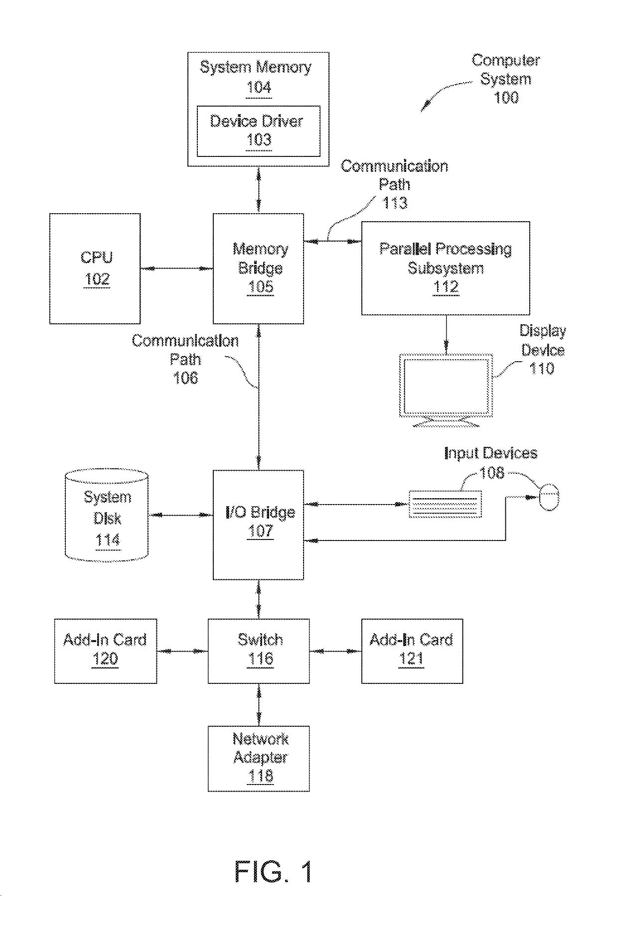
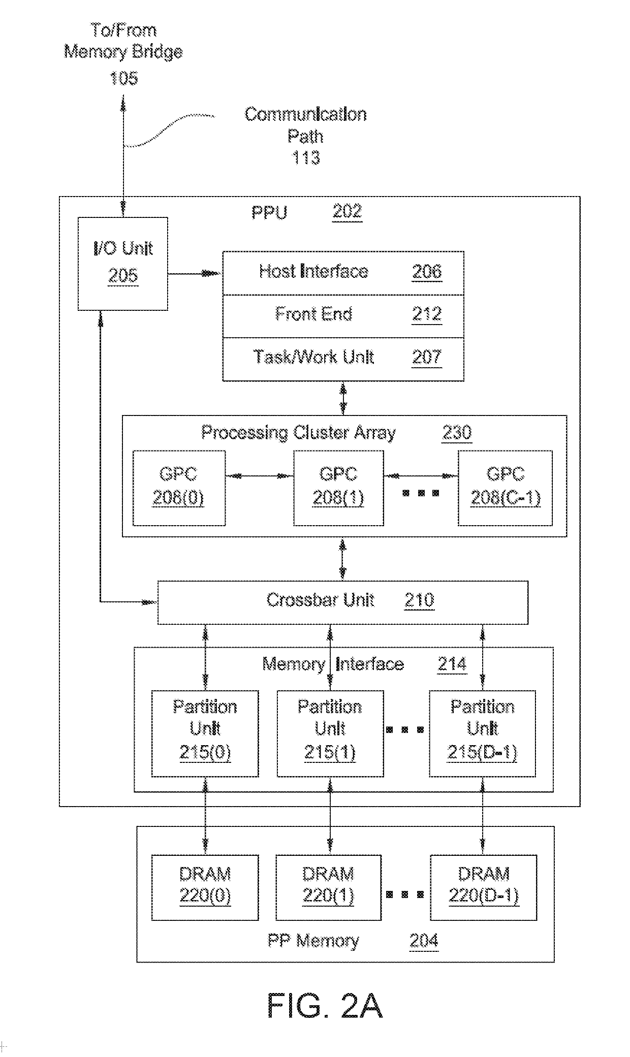
[0001]Various embodiments relate generally to displaying video and, more specifically, to determining allowable locations of tear lines when scanning out rendered data for display.
Description of the Related Art
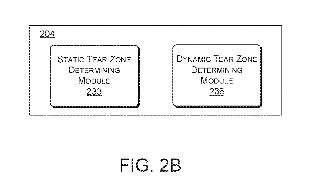
[0002]“Screen tearing” in the form of “tear lines” is an undesirable visual artifact that oftentimes occurs when generating frames of content for display on a display device. A tear line typically appears in a display as a horizontal discontinuity when, for example, a translational shift exists between a portion of a display below the tear line and a portion of the display above the tear line. The tear line creates a torn look to the content being displayed because the edges of objects that are displayed across the tear line fail to align.
[0003]Tear lines usually result when there is motion within the content being rendered for display, and the content is being rendered at a rate that is greater than the refresh rate of the display device. In such situations, a difference in p...
PUM
 Abstract
Description
Claims
Application Information