Neon-tube substitute using light-emitting diodes

Inactive Publication Date: 2010-08-26
LIGHT PRESCRIPTIONS INNOVATORS
View PDF11 Cites 30 Cited by
  • Summary
  • Abstract
  • Description
  • Claims
  • Application Information

AI Technical Summary

Benefits of technology

[0013]Embodiments of the present invention disclose methods of side-firing of unlensed high-brightness LEDs into a tubular annulus. The annulus is typically lighter in weight than a solid tube of the same external diameter, which is advantageous in many uses. Nearly all of the light from a line of LEDs is injected into an annular waveguide. Suitable extraction methods are well known for ejecting this guided light out of the tube. They can be classified as surface or volume scattering. In both cases, not all the scattered light gets immediately out of the tube, since some remains trapped inside the annulus by total internal reflection until again scattered. This helps to smooth out the luminous appearance of the tube as externally viewed, which is advantageous in many uses. In fact, luminous uniformity is often of such high importance that without it no amount of robustness, efficacy, longevity, or lo

Problems solved by technology

The cost per lumen of the low-brightness LEDs, however, is much greater than for high-bri

Method used


Image

  • Neon-tube substitute using light-emitting diodes
  • Neon-tube substitute using light-emitting diodes
  • Neon-tube substitute using light-emitting diodes

Examples


Embodiment Construction

[0030]Corresponding reference characters indicate corresponding components throughout the several views of the drawings.

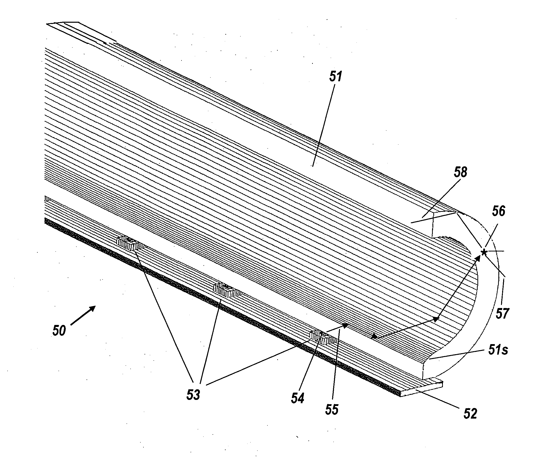
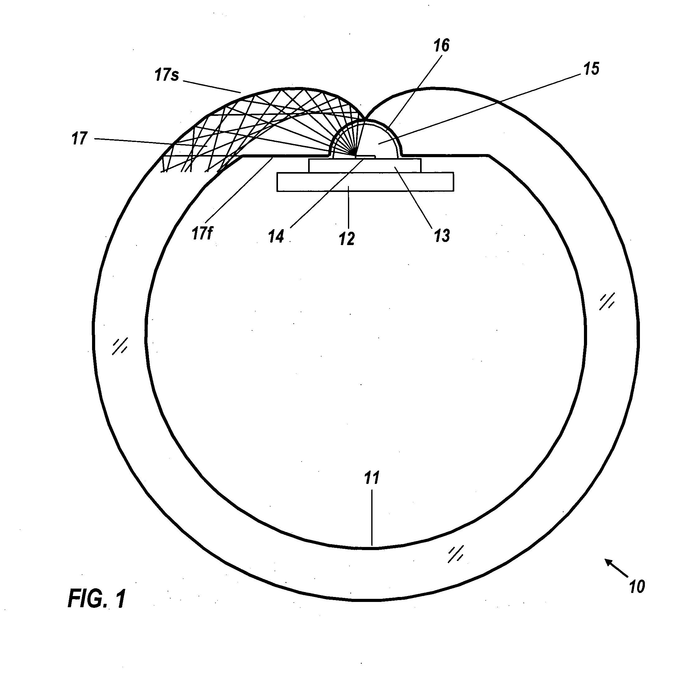
[0031]FIG. 1 shows a cross-section of and embodiment of a tubular luminaire indicated generally by the reference numeral 10. Luminaire 10 comprises transparent hollow tube 11, circuit board 12, LED package 13, LED emitter chip 14, and transparent LED dome 15. Transparent hollow tube 11 comprises circular groove 16 surrounding dome 15, and injector section 17, bounded by upper spiral surface 17s and a lower flat surface 17f. Also shown are some exemplary light rays emitted from the edge of chip 14. All light from chip 14 remains trapped within the wall of tube 11 by total internal reflection, until scattered out by either or both of two mechanisms, weak volume scattering or graded surface scattering. Light from the LEDs undergoes a high number of reflections per average path length. When using surface scattering for ejection, more reflections mean scattering sooner,...


PUM


Abstract

A tubular luminaire efficiently utilizes the light of a line of high-brightness unlensed LEDs to reproduce the homogeneous appearance of a neon tube. The transparent tube has an annular cross-section suitable for cost-effective manufacturing by extrusion. The LEDs are mounted in a line on a circuit board that can be positioned either inside or outside the tube. Their light shines into a cylindrical groove, thereby entering within the material of the tube. Above the groove, the wall of the tube has a spiral shape that reflects the light laterally so that it stays within the annular tube for a considerable path length. Volume scattering by a low density of scattering inclusions causes the light to escape as a homogenous glow. Alternatively, mild surface scattering from the inside surface can be used.

Description

BACKGROUND OF THE INVENTION[0001]The present invention relates generally to illumination and more particularly to LED-based tubular substitutes for the neon lamp. The neon lamp is a venerable and ubiquitous accent light with such technological maturity that no significant improvements are in sight, but with such fragility and high operating voltage (>15,000 V) as to pose inescapable risks. For example, fragility is so high that long-distance shipping is not economical due to inevitable breakage, and thus most lamps are custom-produced locally by small businesses, precluding the economies of mass production. Of societal significance is the relatively low efficacy of neon lamps, leading to excessive power consumption. Furthermore, neon lamps are volume emitters, leading to their perceived brightness being proportional to the length of the viewer's line of sight through the cylinder. Thus they are highly non-uniform spatially and directionally.[0002]Fluorescent tubes have uniform br...

Claims


Application Information

Patent Timeline
IPC IPC(8): F21V9/16F21S4/00F21V29/00
CPCF21K9/00F21Y2101/02F21Y2103/003F21K9/30G02B6/0096F21K9/20F21K9/61F21Y2103/10F21Y2115/10
Inventor CHAVES, JULIO C.ALVAREZ, ROBERTOPARKYN, WILLIAM A.MINANO, JUAN CARLOS
Owner LIGHT PRESCRIPTIONS INNOVATORS
Why Eureka
Try Eureka