Gear structure spring hinge

a technology of hinges and hinges, applied in the direction of wing openers, doors/window fittings, constructions, etc., can solve the problems of food injury or overturning, and achieve the effect of reducing the closing speed of the cabinet door

Active Publication Date: 2019-06-06
UNIND SHENZHEN CO LTD
View PDF0 Cites 4 Cited by
  • Summary
  • Abstract
  • Description
  • Claims
  • Application Information

AI Technical Summary

Benefits of technology

[0009]Beneficial effects of the present invention are as follows: in the present invention, a first gear is driven by a spring assembly, the first gear driving a second gear meshed therewith, the second gear synchronously driving a cabinet door connected to a connecting arm to close; compared to existing spring hinges, by means of a gear meshed driving mechanism of the present invention, the closing speed of the cabinet door is effectively reduced, and an effect of damping is achieved, such that the cabinet door is closed in a more stable manner, and a force of the spring assembly is not affected after the spring assembly drives the cabinet door to close. The present invention is particularly suitable for use on such products as ovens and microwave ovens.

Problems solved by technology

An excessively high closing speed of the cabinet door easily causes injuries or overturning of food.

Method used


Image

  • Gear structure spring hinge
  • Gear structure spring hinge

Examples


Embodiment Construction

[0014]A structure of the present invention is further described below in connection with the accompanying drawings and particular preferred embodiments of the present utility model.

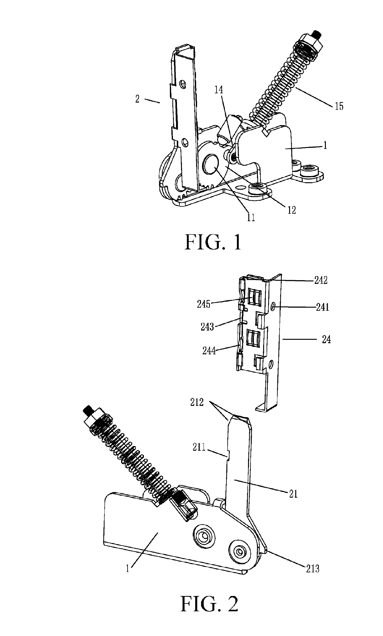
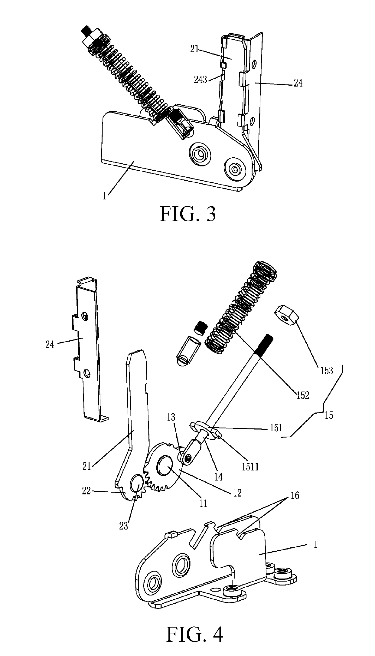
[0015]Referring to FIGS. 1-4, as shown, a gear structure spring hinge of the present invention includes a fixing base 1 and a hinge arm 2. The fixing base 1 is connected to a first gear 12 through a first gear shaft 11, a crank shaft 13 being provided on a gear surface of the first gear 12, the crank shaft 13 being movably connected to a pull rod 14, a spring assembly 15 being sleeved on the pull rod 14, a front end of the spring assembly 15 being mated with and snap-fitted to the fixing base 1. The hinge arm 2 includes a connecting arm 21 and a second gear 22, the second gear 22 being provided on an end of the connecting arm 21, the second gear 22 and the connecting arm 21 forming an integral structure, the second gear 22 being connected to the fixing base 1 through a second gear shaft 23, the second gea...


PUM


Abstract

The present invention relates to the technical field of spring hinges, and to a gear structure spring hinge, which addresses the technical shortcoming that a closing speed is excessively high when an existing spring hinge used in a household appliance drives a cabinet door to close. The gear structure spring hinge comprises a fixing base and a hinge arm, the fixing base being connected to a first gear through a first gear shaft, a crank shaft being provided on a gear surface of the first gear, the crank shaft being movably connected to a pull rod, a spring assembly being sleeved on the pull rod, a front end of the spring assembly being mated with and snap-fitted to the fixing base; and the hinge arm includes a connecting arm and a second gear, the second gear being provided on an end of the connecting arm, the second gear and the connecting arm forming an integral structure, the second gear being connected to the fixing base through a second gear shaft, the second gear being meshed with the first gear. Compared to the existing spring hinge, by means of the present invention, the closing speed of the cabinet door is effectively reduced, and an effect of damping is achieved, such that the cabinet door is closed in a more stable manner, and a force of the spring assembly is not affected after the spring assembly drives the cabinet door to close. The present invention is particularly suitable for use on such products as ovens and microwave ovens.

Description

BACKGROUNDTechnical Field[0001]The present invention relates to the technical field of spring hinges, and in particular to a spring hinge used in household appliances that is connected between a main body and a cabinet door for assisting in elastically closing the cabinet door.Related Art[0002]For an existing spring hinge used in a household appliance, to ensure that a cabinet door can be satisfactorily closed and at the same time the cabinet door can be kept in an open and stationary state in the process of taking out an article from a cabinet body or placing an article in the cabinet body after the cabinet door is opened without applying an external force to the cabinet door, a spring and eccentric cam combination mechanism is generally adopted. However, for the existing spring hinge, in the process of closing the cabinet door, after the cabinet door passes through a stationary position, the cabinet door is freely closed at a relatively large acceleration under the action of a spr...

Claims


Application Information

Patent Timeline
Patent Type & Authority Applications(United States)
IPC IPC(8): E05F1/12E05D11/06E05D3/12
CPCE05F1/1253E05D11/06E05D3/122E05F3/20E05Y2201/224E05Y2900/308E05Y2900/30E05D3/02E05F1/1058E05F1/1261E05F1/14E05Y2201/638E05Y2201/71E05Y2201/712E05Y2600/626
Inventor HU, NENGJUNCHENG, MEIYUAN
Owner UNIND SHENZHEN CO LTD
Why Eureka
Try Eureka