Vacuum circuit breaker

a circuit breaker and vacuum technology, applied in the direction of air breakers, high-tension/heavy-dress switches, contacts, etc., can solve the problems of collision speed v the impact energy e, and the inability of the mechanism to produce a reduced closing so as to improve the initial opening speed of the moving electrode, improve the interruption performance, and reduce the damage to the contact face

Active Publication Date: 2013-04-23
MEIDENSHA ELECTRIC MFG CO LTD
View PDF9 Cites 5 Cited by
  • Summary
  • Abstract
  • Description
  • Claims
  • Application Information

AI Technical Summary

Benefits of technology

[0012]An advantage of the present invention is to provide a vacuum circuit breaker that offers an extended service lifetime rendered by an increased initial opening speed of a moving electrode with an improved interruption performance, a reduced contact face damage on a moving and a fixed electrodes, and an improved voltage withstand performance between electrodes and enhanced interruption performance.
[0013]The vacuum circuit breaker according to the present invention has a bulb, the bulb having an insulative vacuum tube; a fixed electrode fixed at the end of a current-carrying conductor and a moving electrode fixed at the end of another current-carrying conductor, the both electrodes being arranged in the insulative vacuum tube with contact faces of thoseof being opposed each other; and an operation system for the current-carrying conductor of the moving electrode equipped with a compression-spring, in which the operation system is equipped with an auxiliary compression-spring in such an arrangement that the auxiliary compression-spring ceases energizing in the middle of a circuit breaking movement of the moving electrode, and begins storing spring energy in the middle of a circuit closing movement of the moving electrode.
[0014]It is preferable that an intermediate connecting rod forming a part of the operation system should be engaged with the current-carrying conductor of the moving electrode, and that the compression-spring and the auxiliary compression-spring should be coaxially arranged with the current-carrying conductor at the engaging portion where the current-carrying conductor of the moving electrode engages with the intermediate connecting rod.
[0015]It further is preferable that the auxiliary compression-spring should have a larger spring constant than that of the compression-spring.Effect of Invention
[0016]Such a configuration of the compression-spring and the auxiliary compression-spring as is defined in the present invention permits the manufacturing of a vacuum circuit breaker to be economical. Because, in the opening operation to open the moving electrode, the auxiliary compression-spring still continues to expand even after the moving electrode was separated from the fixed electrode, the initial breaking speed of the moving electrode can be increased with an improved interruption performance. Therefore, no large-sized operating device is demanded and accordingly manufacturing is economized. In the closing operation for the moving electrode, the auxiliary compression-spring reduces the closing speed of the moving electrode to a proper extent. This avoids the bouncing between the moving and the fixed electrodes and largely reduces damages on the electrodes with an improved voltage withstand performance between electrodes and the interruption performance, attaining an extended service life of a vacuum circuit breaker.

Problems solved by technology

Employing the single pressing-spring style involves a difficulty in the adjusting of the pressing force to a proper contact pressure on a set of moving and fixed electrodes; inadequate spring pressure of the pressing-spring does not give a proper assisting force to the operation of the operating device. FIG. 5 indicates a stroke characteristic of moving electrodes in terms of time, wherein T represents the time-elapse for movement of the moving electrode and St the traveling stroke of the electrode.
This time-stroke characteristic prevents an improved interruption characteristic since operating the moving electrode through a operating device working on a single pressing-spring cannot produce a higher initial opening speed.
Further, the single spring mechanism cannot produce a reduced closing speed of the moving electrode, which causes the impact energy E (=kmv2), given by a constant k, the mass m, and the collision speed v of the moving electrode, to become large.
Such larger energy easily causes bouncing between the contact faces of the moving and the fixed electrodes developing into such a problem as invites a serious contact face damage.

Method used


Image

  • Vacuum circuit breaker
  • Vacuum circuit breaker
  • Vacuum circuit breaker

Examples


embodiment 1

[Embodiment 1]

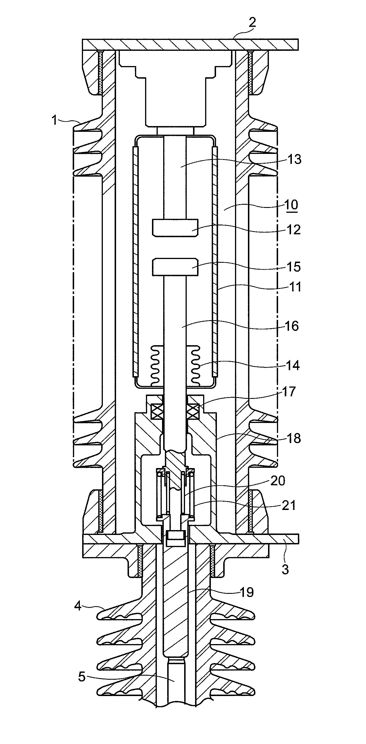
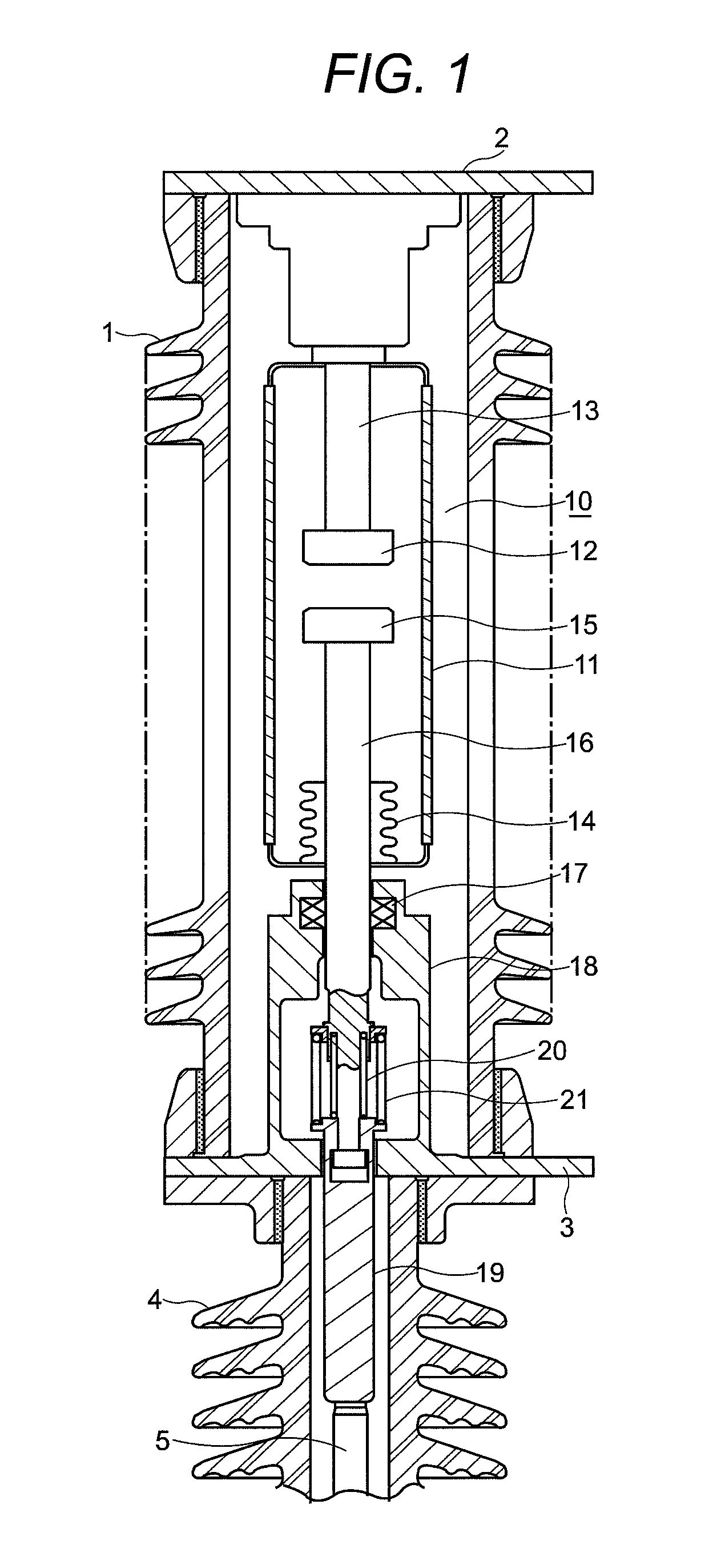
[0023]The following explains an example of embodiments of the vacuum circuit breaker by the present invention illustrated in figures. The example of the vacuum circuit breaker shown in FIG. 1 is an live tank type vacuum circuit breaker. This breaker has such a construction that a main body of bulb 10 is accommodated in a porcelain bushing 1, that terminals 2 and 3 are arranged on the top and the bottom faces of the porcelain bushing 1, and that the inside thereof is filled with insulating gas.

[0024]The porcelain bushing 1 is supported by a hollow supporting insulator 4 to assure an insulating separation. An insulative manipulation rod 5, which connects to a lever (not shown) or a similar device on a operating device through the supporting insulator 4, manipulates the main body of bulb 10 for open-close.

[0025]The main body of bulb 10, which is the major part of the vacuum circuit breaker, is made of an insulative vacuum tube 11 of ceramic and inside of which is kept vac...


PUM


Abstract

Vacuum circuit breakers are to gain an extended lifetime by reducing contact face damage of moving and fixed electrodes with improved voltage withstand performance therebetween and enhanced interruption performance. Vacuum circuit breaker of the present invention has bulb 10 having: insulative vacuum tube 11; and fixed electrode 12 on end of current-carrying conductor 13 and moving electrode 15 on end of another current-carrying conductor 16 arranged in insulative vacuum tube 11 with their electrode contact faces opposed each other. Operation system for manipulating current-carrying conductor 16 of moving electrode 15 is equipped with compression-spring 20 and auxiliary compression-spring 21 that increases initial opening speed of moving electrode 15. Auxiliary compression-spring 21 ceases energizing in the middle of a circuit breaking movement of moving electrode 15 and begins storing spring energy in the middle of a circuit closing movement of the same.

Description

TECHNICAL FIELD[0001]The present invention relates to a vacuum circuit breaker, more particularly relates to such a vacuum circuit breaker as has a compression-spring to apply a contact pressure to a set a moving contact and a fixed contact.BACKGROUND ART[0002]In general, a vacuum circuit breaker is widely used in electrical equipment in substations or in distribution systems on account of its capability in interrupting a large current with a small sized structure. The construction of a main body of bulb in a vacuum circuit breaker is such that a set of a fixed electrode fixed at the end of face of a current-carrying conductor and a moving electrode fixed similarly on the end face of another current-carrying conductor disposed facing each other is accommodated in an insulative vacuum tube of ceramic or similar material kept vacuum. The main body of bulb is used in a vacuum circuit breaker, being installed in an atmospheric environment or in an insulating gas atmosphere, wherein an o...

Claims


Application Information

Patent Timeline
Patent Type & Authority Patents(United States)
IPC IPC(8): H01H33/666
CPCH01H1/50H01H33/666
Inventor NAGATAKE, KAZUHIROKOBAYASHI, TOORUMATSUI, YOSHIHIKO
Owner MEIDENSHA ELECTRIC MFG CO LTD
Why Eureka
Try Eureka