Lever action automatic shootbolt operator with magnetically-triggered lock mechanism

a technology of automatic trigger and lever action, which is applied in the direction of construction, building locks, construction fastening devices, etc., can solve the problems of insufficient assurance, unsafe conditions, and disadvantages of known bolt assemblies

Active Publication Date: 2020-02-13
INTERLOCK USA
View PDF0 Cites 5 Cited by
  • Summary
  • Abstract
  • Description
  • Claims
  • Application Information

AI Technical Summary

Benefits of technology

[0006]It is another object of the present invention to provide an improved concealed lever operator for a bolt assembly which utilizes a lever on a two bar linkage to drive a series of rack and pinion gears to create a mechanical advantage to retract and / or extend shoot bolts.
[0008]It is another object of the present invention to provide an improved triggered bolt assembly for preventing access to the interior of an enclosure.
[0009]It is still another object of the present invention to provide an improved bolt assembly which ensures that the bolt is extended only after the two components are in the appropriate position relative to each other.
[0010]A further object of the present invention is to provide a magnetically-triggered bolt assembly which ensures that the bolt is extended only after the two components are in the appropriate position relative to each other.
[0041]In an embodiment, the lever operator may further include a spring normally biasing the second slider towards the first relative position, the second slider compressing the spring as the lever or handle is rotated to the second position, wherein expansion of the spring after release of the lever or handle causes the lever or handle to return to the first position via translation of the first and second sliders from the second relative position to the first relative position. The lever operator may further include a damper for reducing closing speed of the lever or handle as the lever or handle is released from the second position and the first and second sliders translate from the second relative position to the first relative position, and the damper may be a linear damper contacting a bottom end of the second slider.

Problems solved by technology

However, known bolt assemblies have disadvantages.
For example, in bolt assemblies including a key, if the key is actuated to extend the bolt in circumstances where it is presumed that the two components of the bolt assembly are interengaged by the bolt but in fact the two components are not interengaged, unsafe conditions may prevail despite the bolt being extended.
In a two component bolt assembly, it is not sufficient to ensure simply that the bolt is extended, as it may be that the bolt when extended has not engaged the other component of the assembly.

Method used


Image

  • Lever action automatic shootbolt operator with magnetically-triggered lock mechanism
  • Lever action automatic shootbolt operator with magnetically-triggered lock mechanism
  • Lever action automatic shootbolt operator with magnetically-triggered lock mechanism

Examples


Embodiment Construction

)

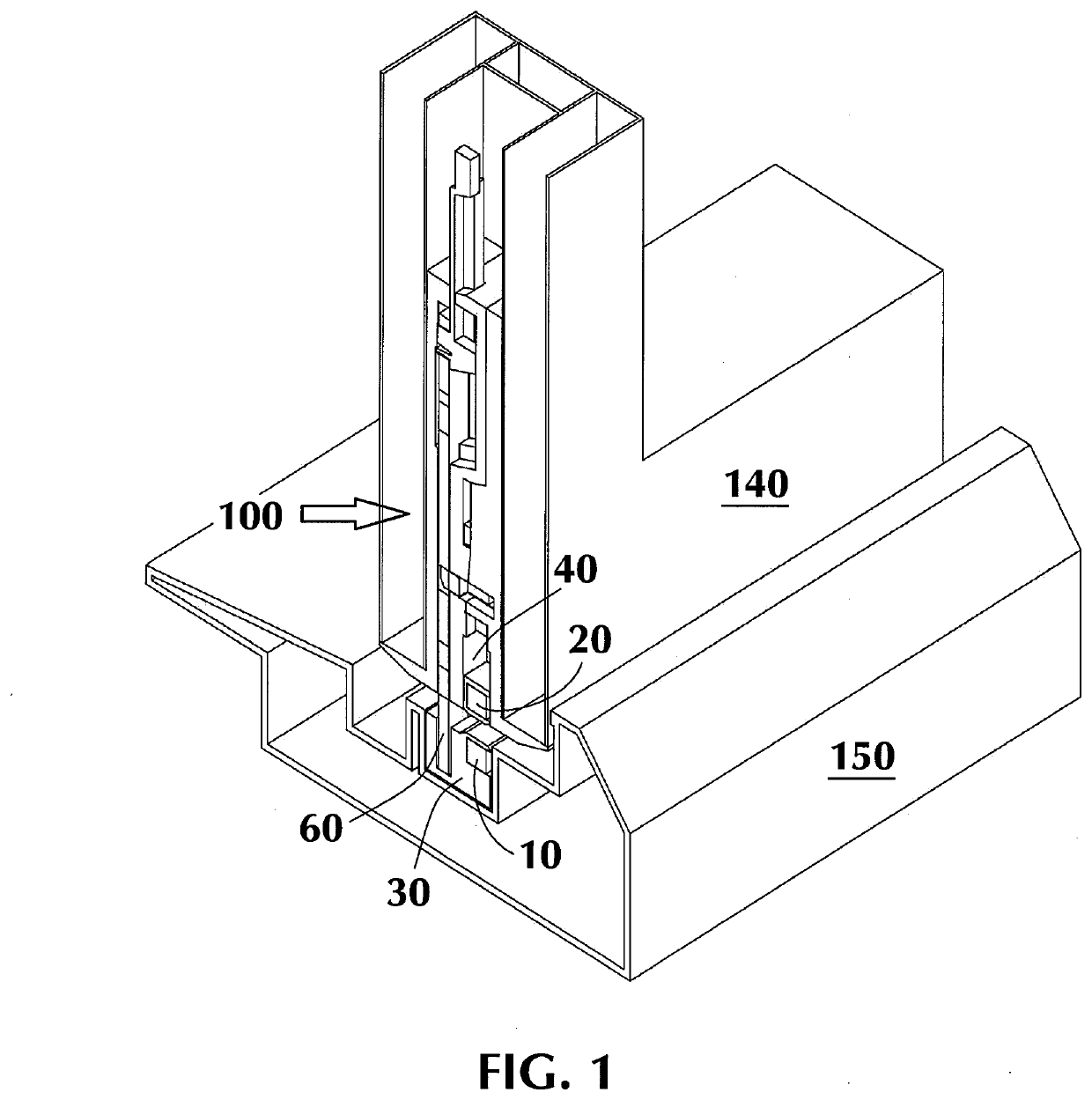
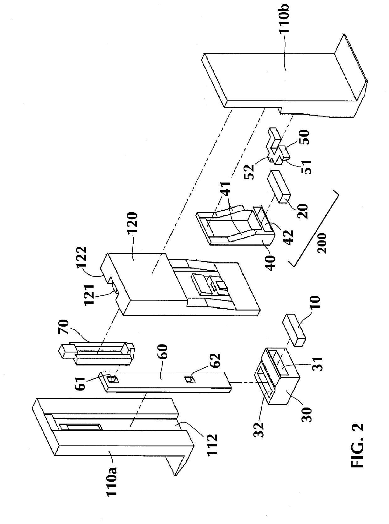
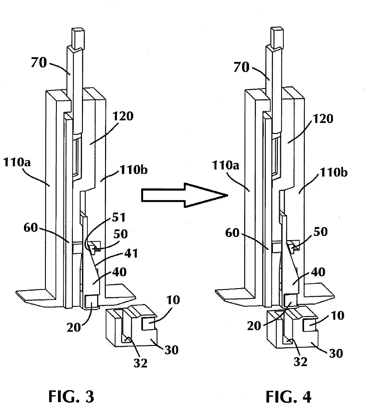
[0084]In describing the embodiments of the present invention, reference will be made herein to FIGS. 1-33 of the drawings, in which like numerals refer to like features of the invention.

[0085]Certain terminology is used herein for convenience only and is not to be taken as a limitation of the invention. For example, words such as “upper,”“lower,”“left,”“right,”“horizontal,”“vertical,”“upward,”“downward,”“clockwise,” and “counterclockwise” merely describe the configuration shown in the drawings. Indeed, the referenced components may be oriented in any direction and the terminology, therefore, should be understood as encompassing such variations unless specified otherwise. For purposes of clarity, the same reference numbers will be used in the drawings to identify similar elements.

[0086]Additionally, in the subject description, the words “exemplary,”“illustrative,” or the like are used to mean serving as an example, instance or illustration. Any aspect or design described herein as “...


PUM


Abstract

A magnetically-triggered lock mechanism for interengaging two relatively movable components. The lock mechanism includes a bolt mounted within a first component composed of a first material and displaceable between retracted and extended positions to interengage with a second component when the first and second components are in a predetermined position relative to each other and the bolt is extended, and a magnetically-releasable latch mechanism positioned to latch the bolt in a retracted position, the latch mechanism including a first magnet and mounted for movement between a biased latch engaging position and a latch releasing position. A support collar composed of a second material having higher strength than that of the first material is disposed around the bolt between an inner casing and outer casing of the first component and is spaced from the bolt to allow for sliding movement of the bolt through the support collar as the bolt moves between the extended and retracted positions. The support collar absorbs and distributes to the inner and / or outer casing a load generated from the bolt as the bolt moves to the extended position through the support collar. A second magnet is positioned to displace the latch mechanism to the latch releasing position when the first component is in the predetermined position relative to the second component.

Description

BACKGROUND OF THE INVENTION1. Field of the Invention[0001]The present invention relates generally to a lever action operator and triggered bolt assembly for engaging two relatively movable components. More specifically, the present invention relates to a concealed lever mechanism for driving a magnetically-triggered bolt assembly for engaging a window or door with a strike or frame to prevent access to the interior of an enclosure.2. Description of Related Art[0002]Bolt assemblies are a well-known means for preventing access to the interior of an enclosure or structure. Known bolt assemblies comprise two components, one of which is connected to one component of an enclosure, such as a door or window frame, and the other connected to the other component, such as a door. The first component typically includes a bolt displaceable between engaged and disengaged positions, and the second component comprises a socket into which the bolt may be extended when the two components are in an ap...

Claims


Application Information

Patent Timeline
Patent Type & Authority Applications(United States)
IPC IPC(8): E05B47/00E05B47/02E05C19/16
CPCE05B47/0002E05B47/023E05B2047/0008E05C19/168E05B47/004E05B47/0038E05B63/20E05B53/003E05B15/022E05B15/025E05C9/041E05B47/0046E05C9/12E05C9/20
Inventor MINTER, PETER J.STADLER, DOUGLASFULLENWIDER, MARC WESLEYFRABBIELE, ANTHONY J.
Owner INTERLOCK USA
Why Eureka
Try Eureka