Microelectromechanical and/or nanoelectromechanical device offering improved robustness

a micro-electromechanical and nano-electromechanical technology, applied in the direction of microstructural technology, piezoelectric/electrostrictive devices, acceleration measurement using interia forces, etc., can solve the problems of device weakened reducing the flexibility and robustness of the sensor, and concentrating strain at the level of the hing

Active Publication Date: 2019-06-13
COMMISSARIAT A LENERGIE ATOMIQUE ET AUX ENERGIES ALTERNATIVES
View PDF0 Cites 3 Cited by
  • Summary
  • Abstract
  • Description
  • Claims
  • Application Information

AI Technical Summary

Benefits of technology

[0007]It is consequently an aim of the present invention to offer a MEMS and / or NEMS device offering increased flexibility and robustness.

Problems solved by technology

However the implementation of a hinge or pivot joint between the mass and the fixed part can reduce the flexibility and the robustness of the sensor, indeed the device may be weakened at the level of the hinge.
Moreover, there may be a concentration of strain at the level of the hinge.

Method used


Image

  • Microelectromechanical and/or nanoelectromechanical device offering improved robustness
  • Microelectromechanical and/or nanoelectromechanical device offering improved robustness
  • Microelectromechanical and/or nanoelectromechanical device offering improved robustness

Examples


Embodiment Construction

[0007]It is consequently an aim of the present invention to offer a MEMS and / or NEMS device offering increased flexibility and robustness.

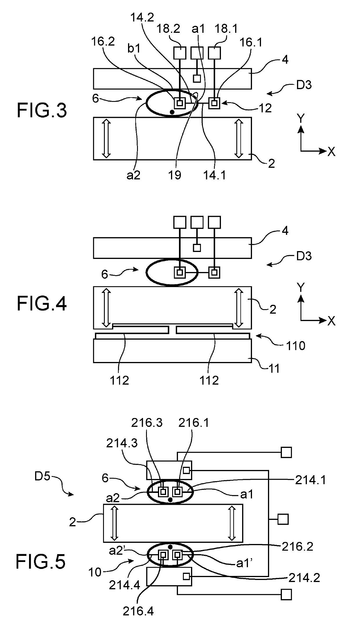
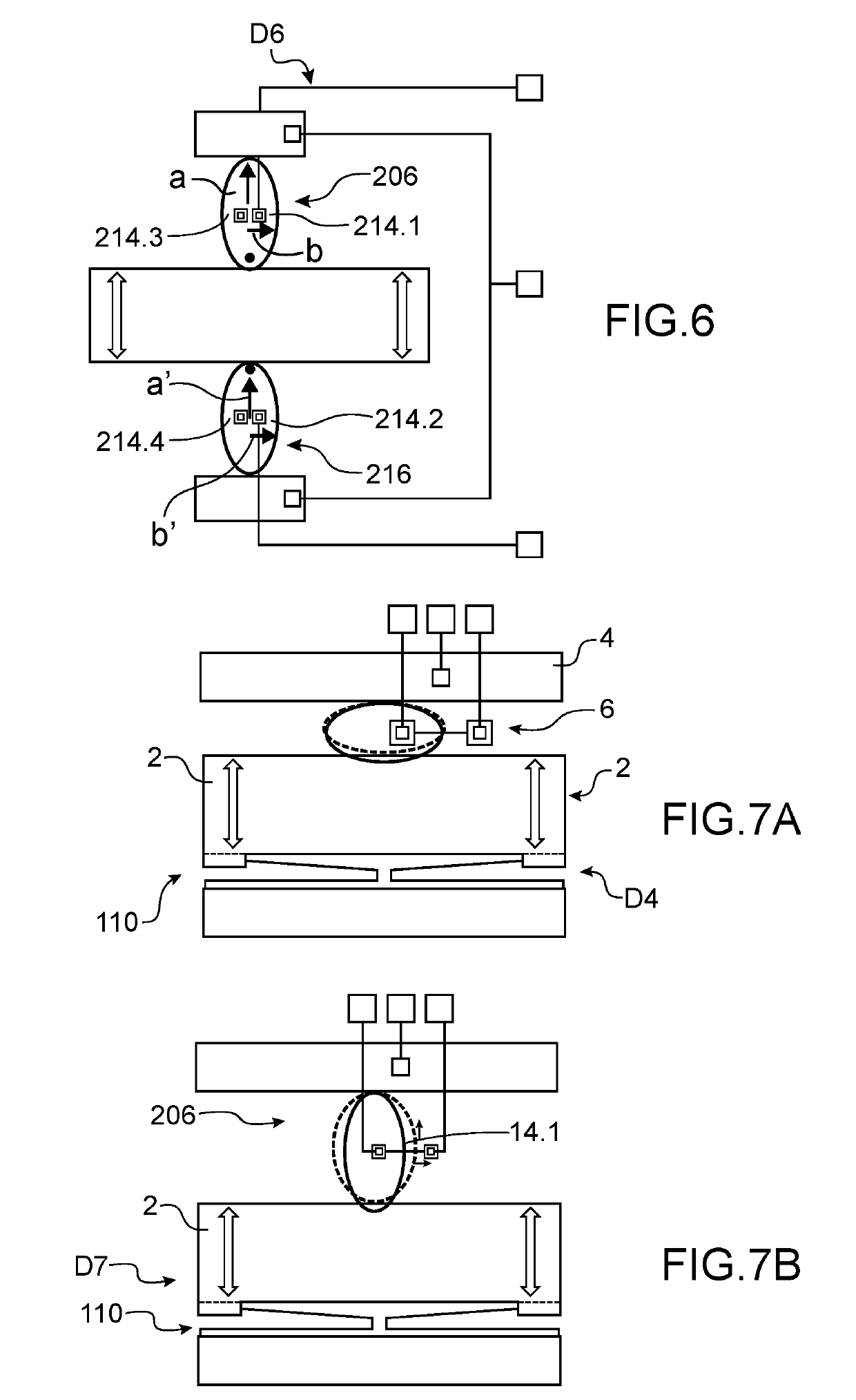
[0008]The aforesaid aim is attained by a device comprising a fixed part with respect to the substrate and a part suspended with respect to said fixed part by suspension means, said suspended part being intended to be displaced in the plane of the device. The suspension means comprise at least one element connected by a first end directly to the suspended part and by a second end to the fixed part, said element comprising a curved shape extending from its first end to its second end.

[0009]The suspension element is intended to be loaded only in an elastic manner. It does not comprise several portions connected so as to form angular zones. Thus, it does not comprise a fragile zone and has great robustness.

[0010]The suspension means of curved shape ensure guiding, by introducing flexibility in the desired direction of displacement, and stiffness in th...


PUM

PropertyMeasurementUnit
shapeaaaaaaaaaa
displacementaaaaaaaaaa
forcesaaaaaaaaaa

Abstract

Microelectromechanical and / or nanoelectromechanical device comprising a fixed part (4), at least one suspended part (2) intended to be moveable in the plane of said device with respect to the fixed part (4) along at least one first direction (Y), a first means (6) for suspending said suspended part (2), said first suspension means (6) comprising two suspension elements (8.1, 8.2) each suspension element (8.1, 8.2) comprising a first end fixed directly to the suspended part (2) and a second end connected to the fixed part (4), each suspension element (8.1, 8.2) having a half-ellipse shape in the plane and extending between the first end and the second end, the two suspension elements (8.1, 8.2) being arranged with respect to each other so as to form an ellipse.

Description

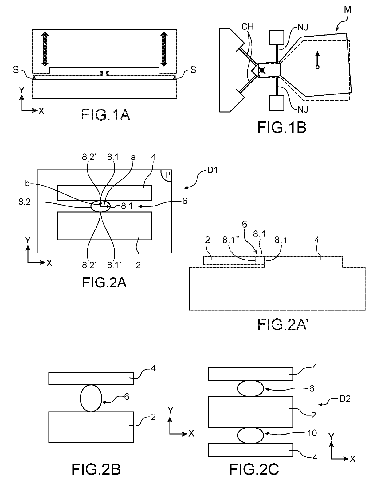
TECHNICAL FIELD AND PRIOR ART[0001]The present invention relates to a microelectromechanical and / or nanoelectromechanical device offering increased flexibility and robustness.[0002]Microelectromechanical system (MEMS) and / or nanoelectromechanical system (NEMS) devices are used to produce miniaturised sensors such as accelerometers, gyrometers, pressure sensors, microphones, and miniaturised actuators for example to produce orientable micro-mirrors.[0003]MEMS and / or NEMS devices comprise at least one suspended moveable element. In the case of an accelerometer, the moveable element or mass is displaced under the effect of an acceleration force. Its displacement is measured, which makes it possible to determine the acceleration value.[0004]MEMS and / or NEMS devices may implement suspension means S comprising beams connected together by their ends in zigzag shape, as is represented in FIG. 1A. During the displacement of the moveable element, the suspension means deform: the beams move aw...

Claims


Application Information

Patent Timeline
Patent Type & Authority Applications(United States)
IPC IPC(8): B81B3/00G01P15/12G01L1/18
CPCB81B3/0018B81B3/0051G01P15/123G01L1/18B81B2201/0228B81B2203/0172B81B2203/0163B81B3/0078B81B2203/0118B81B2203/051B81B2207/053G01C19/5762
Inventor LHERMET, HELENE
Owner COMMISSARIAT A LENERGIE ATOMIQUE ET AUX ENERGIES ALTERNATIVES
Why Eureka
Try Eureka