Centrifugal blower assembly and method for assembling the same

a centrifugal blower and assembly technology, which is applied in the direction of non-positive displacement fluid engines, radial flow pumps, pump components, etc., can solve the problems of reducing the overall efficiency of the centrifugal blower, increasing the noise generated, and reducing the uniform flow of discharge air at the outl

a centrifugal blower and assembly technology, which is applied in the direction of non-positive displacement fluid engines, radial flow pumps, pump components, etc., can solve the problems of reducing the overall efficiency of the centrifugal blower, increasing the noise generated, and reducing the uniform flow of discharge air at the outl

US20190186499A1Active Publication Date: 2019-06-20REGAL BELOIT AMERICA

Image

  • Centrifugal blower assembly and method for assembling the same
  • Centrifugal blower assembly and method for assembling the same
  • Centrifugal blower assembly and method for assembling the same

Examples


Embodiment Construction

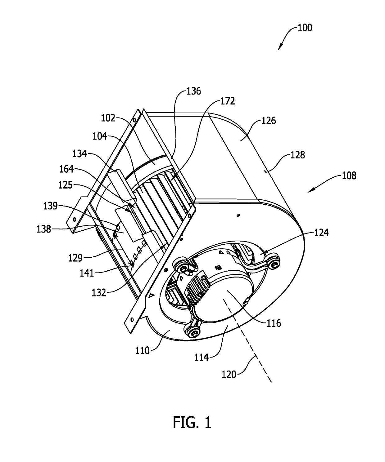
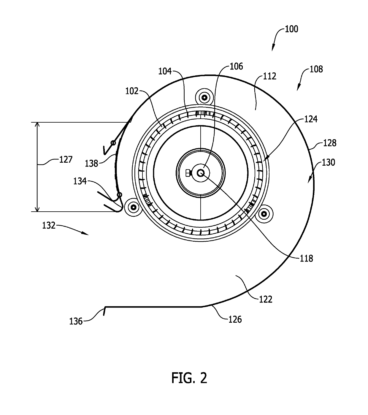
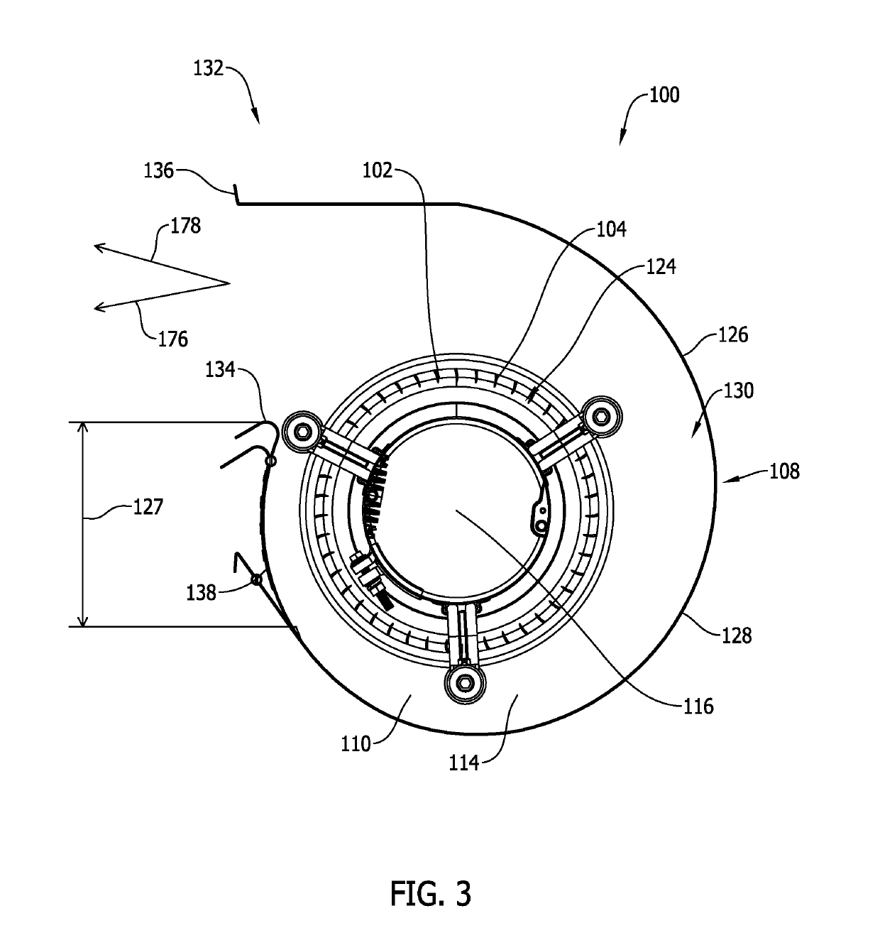
[0032]The embodiments described herein relate to a centrifugal fan housing. More specifically, embodiments relate to a centrifugal fan housing including a cutoff that is adjustable or a fixed cutoff with aerodynamic and acoustic geometries. FIG. 1 illustrates an exemplary embodiment of a centrifugal blower assembly 100. FIG. 2 is a right side view of centrifugal blower assembly 100 shown in FIG. 1 with a right side panel removed. FIG. 3 is a left side view of centrifugal blower assembly 100 shown in FIG. 1 with a left side panel removed. FIG. 4 is a front view of centrifugal blower assembly 100 shown in FIG. 1. Blower assembly 100 includes at least one wheel 102 that includes a plurality of fan blades 104 positioned circumferentially about wheel 102. Wheel 102 is further coupled to a wheel hub 106. Blower 100 further includes a housing 108 comprising a rear portion 110 and a front portion 112. Rear portion 110 includes a sidewall 114 through which a motor 116 is inserted. Motor 116 ...


PUM


Abstract

A centrifugal blower assembly includes a scroll wall, a pair of opposing sidewalls, and an adjustable cutoff plate. The scroll wall is positioned between the pair of opposing sidewalls such that the scroll wall and opposing sidewalls together define a blower chamber and a blower outlet. The scroll wall extends circumferentially between a cutoff point to an end point and defines a cutout extending circumferentially from the cutoff point. The scroll wall, the pair of opposing sidewalls, and the cutoff point define a blower outlet. The blower outlet defines a blower outlet area. The adjustable cutoff plate is adjustably positioned within the cutout to define a notch defining a notch area. The notch area and the blower outlet area define a total blower outlet area.

Description

CROSS REFERENCE TO RELATED APPLICATIONS[0001]This application claims the benefit of and priority to U.S. Provisional Patent Application Ser. No. 62 / 599,170, filed Dec. 15, 2017, which is incorporated herein by reference in its entirety.BACKGROUND[0002]The field of the disclosure relates generally to a housing for a centrifugal fan, and more specifically, to methods and apparatus for an adjustable centrifugal blower discharge.[0003]Centrifugal fans or blowers are commonly used in the automotive, air handling and ventilation industries for directing large volumes of forced air, over a wide range of pressures, through a variety of air conditioning components. In a known centrifugal blower, air is drawn into a housing through one or more inlet openings by a rotating wheel. This air is then forced around the housing and out an outlet end that includes a cutoff point where a casing of the centrifugal blower intersects a discharge of the centrifugal blower. Known centrifugal blowers includ...

Claims


Application Information

Patent Timeline
20 Jun 2019
Publication
US20190186499A1
IPC
F04D29/42; F04D17/08; F04D29/44; F04D29/62
CPC
F04D29/4226; F04D17/08; F04D29/44; F04D29/62; F04D29/162; F04D29/422
Inventors
PIROUZPANAH, SAHAND; BALAGURU, RAJAVEL