Grommet

Active Publication Date: 2019-06-20
YAZAKI CORP
View PDF0 Cites 0 Cited by
  • Summary
  • Abstract
  • Description
  • Claims
  • Application Information

AI Technical Summary

Benefits of technology

The present invention aims to provide a grommet that can easily align with an anti-rotation rib when attaching an interior grommet to an exterior grommet. The invention includes a mark on the outer surface of the reduced-diameter cylindrical portion that indicates the position of the anti-rotation rib. This makes it easier for the notch portion in the interior grommet to align with the anti-rotation rib when attaching the two grommets together. Overall, this simplifies the attachment process and ensures the grommets align correctly.

Problems solved by technology

Accordingly, it is difficult to attach the grommet interior to the grommet exterior in a manner that a notch portion coincides with the anti-rotation rib.

Method used


Image

  • Grommet
  • Grommet
  • Grommet

Examples


first embodiment

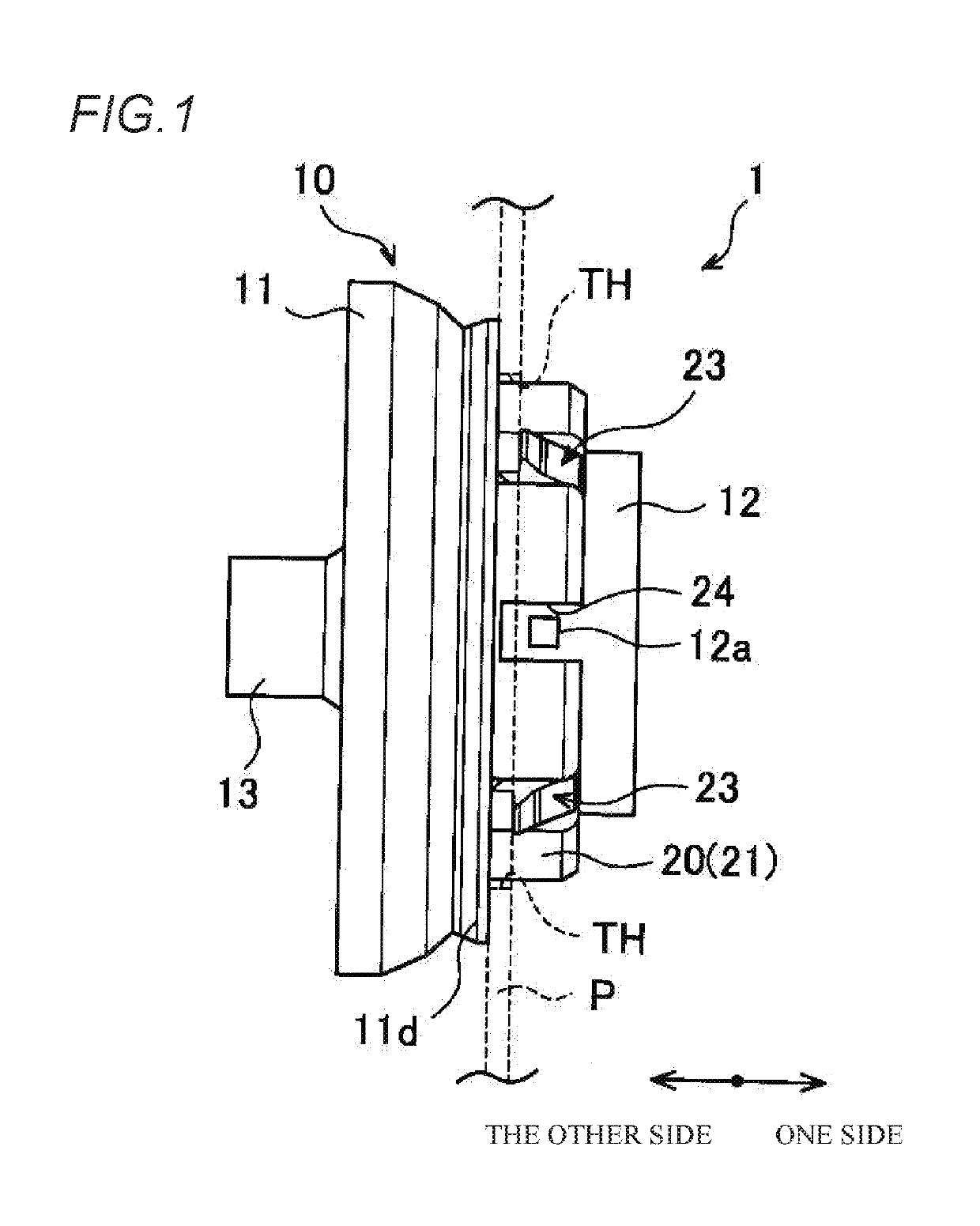
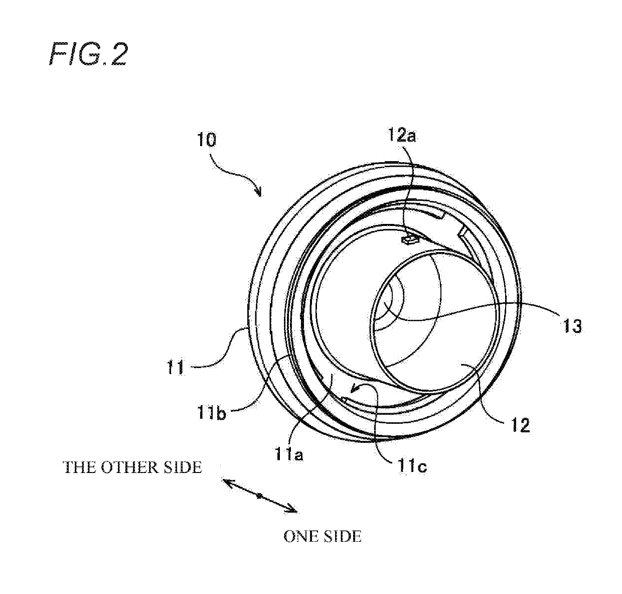
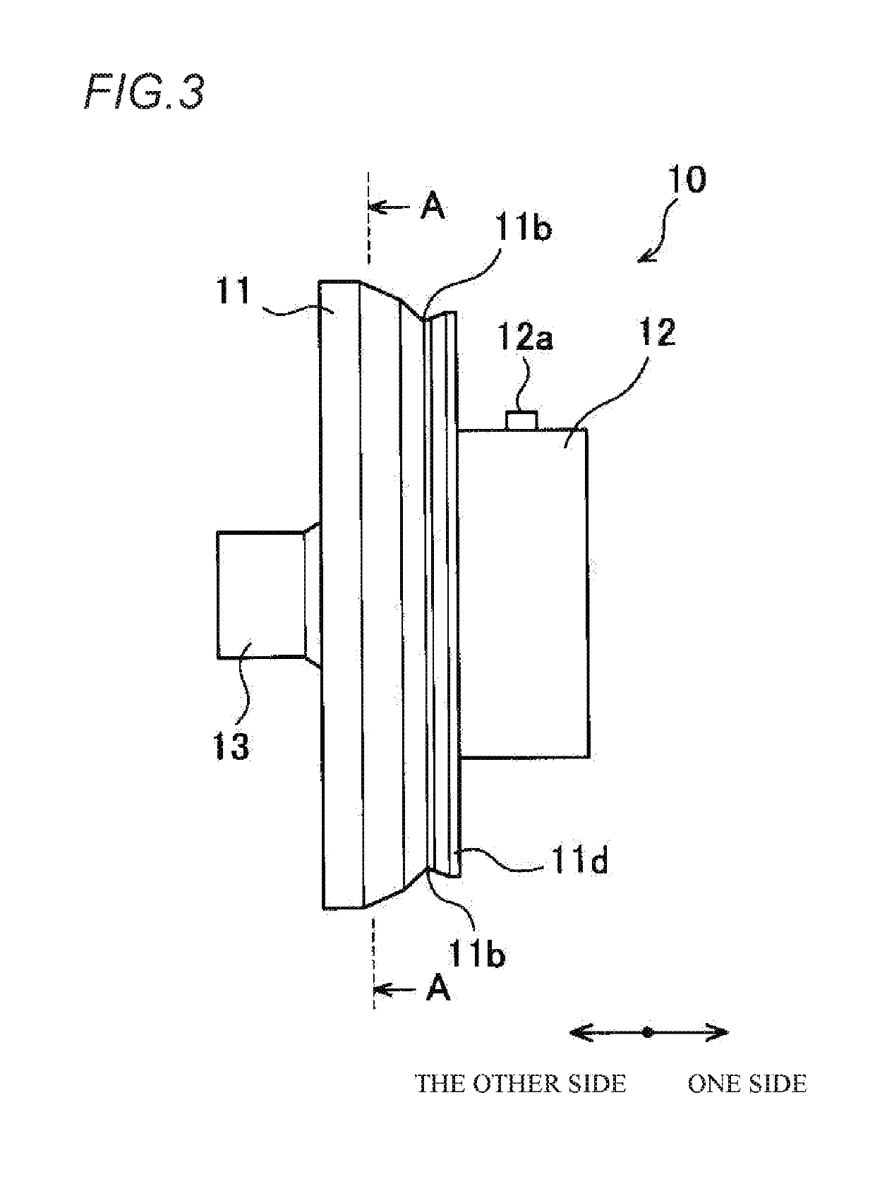
[0023]As illustrated in FIGS. 2 and 3, the first reduced-diameter cylindrical portion 12 and the second reduced-diameter cylindrical portion 13 are cylindrical portions extending in opposite directions from the bottom surface 11a of the large-diameter cylindrical portion 11, and have smaller diameters than that of the large-diameter cylindrical portion 11. In the first embodiment, the first reduced-diameter cylindrical portion 12 has a larger diameter than that of the second reduced-diameter cylindrical portion 13. The first reduced-diameter cylindrical portion 12 includes a protrusion (mark portion) 12a on an outer surface of the first reduced-diameter cylindrical portion 12. Wire harnesses are inserted into the reduced-diameter cylindrical portions 12 and 13.

[0024]The protrusion 12a serves as a mark that indicates a position of the anti-rotation rib 11e. Here, the grommet exterior 10 according to the first embodiment includes the anti-rotation rib lie inside the large-diameter cyl...

second embodiment

[0045]The grommet interior 20 includes a thin portion (not illustrated) inside the cylindrical portion 21, and the protrusion 12a is fitted into the thin portion inside the cylindrical portion 21 when the grommet interior 20 is properly attached to the grommet exterior 10.

[0046]In this way, according to a grommet 2 according to the second embodiment, the notch portion 22a in the flange 22 coincides easily with the anti-rotation rib 11e inside the flange fitting groove 11c, which is similar as in the first embodiment. Further, visibility is enhanced as compared with, for example, a case where the mark portion is a colored portion or the like.

[0047]In the second embodiment, a connecting part of the half bodies 20a and 20b is in the same position as the notch portion 22a in the rotation direction. Therefore, the grommet interior 20 is not limited to a case of being assembled such that the notch portion 22a passes over the protrusion 12a, and may also be assembled such that the connect...


PUM


Abstract

A grommet is formed by integrally fitting a substantially annular flange of a grommet interior to a substantially annular flange fitting groove of a grommet exterior. The grommet exterior includes a large-diameter cylindrical portion in which the flange fitting groove is formed inside, an anti-rotation rib that projects from the flange fitting groove toward inside of the large-diameter cylindrical portion, and a first reduced-diameter cylindrical portion that is provided on an attachment side of the grommet interior to the large-diameter cylindrical portion and that has a diameter smaller than that of the large-diameter cylindrical portion. The flange of the grommet interior is provided with a notch portion into which the anti-rotation rib is fitted. Further, the first reduced-diameter cylindrical portion includes a protrusion on the outer surface thereof that indicates the position of the anti-rotation rib.

Description

CROSS-REFERENCE TO RELATED APPLICATIONS[0001]This application is based on and claims priority under 35 USC 119 from Japanese Patent Application No. 2017-240327 filed on Dec. 15, 2017, the contents of which are incorporated herein by reference.TECHNICAL FIELD[0002]The present invention relates to a grommet.BACKGROUND ART[0003]There is proposed a grommet in which a flange of a grommet interior and a flange fitting groove of a grommet exterior are integrally fitted. In order to prevent rotation of the grommet interior, the grommet includes a dent portion and a projecting portion in the flange and the flange fitting groove, so that the flange and the flange fitting groove are engaged.PRIOR ART DOCUMENTPatent Document[0004]Patent Document 1: JP-A-2003-70133SUMMARY OF INVENTION[0005]However, in the grommet disclosed in Patent Document 1, an anti-rotation rib is hardly seen from outside of the grommet exterior when the anti-rotation rib is provided in the flange fitting groove. Accordingly...

Claims


Application Information

Patent Timeline
IPC IPC(8): F16F1/373F16B43/02
CPCF16F1/3732F16B43/02B60R16/0222
Inventor NAMIKI, SHINTAROUEMATSU, SATOSHI
Owner YAZAKI CORP
Why Eureka
Try Eureka