Optical structure

a technology of optical structure and optical axis, applied in the field of optical structure, can solve the problem of large optical structure, and achieve the effect of easy adjustmen

Active Publication Date: 2018-07-12
HAMAMATSU PHOTONICS KK
View PDF0 Cites 0 Cited by
  • Summary
  • Abstract
  • Description
  • Claims
  • Application Information

AI Technical Summary

Benefits of technology

[0014]In this case, since the first polarized light and the second polarized light with the second wavelength (λ2) can be controlled with different diffraction conditions, an angle of deflection caused by diffraction can be easily adjusted, and the coincidence of the traveling directions can be easily achieved.
[0015]In a fourth optical structure, the polarizing beam splitter and the diffractive optical element are integra

Problems solved by technology

However, in the case of this conventional method, since a plurality of Wollaston pris

Method used


Image

  • Optical structure
  • Optical structure
  • Optical structure

Examples


first embodiment

[0041]FIG. 3 is a diagram illustrating an optical structure according to a

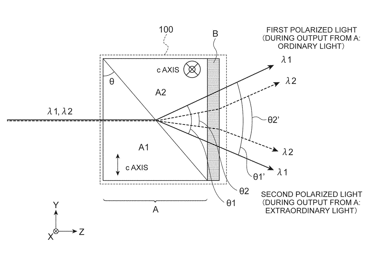
[0042]An optical structure 100 includes a polarizing beam splitter A that splits input light input from an incoming plane into first polarized light and second polarized light, and diffractive optical element B (diffraction means: a diffraction grating or a spatial light modulator.)

[0043]that is disposed at a stage subsequent to the polarizing beam splitter A and has a plurality of light transmission regions separated at a prescribed pitch. Split angles in the polarizing beam splitter A, which are angles formed by the traveling directions of the rays of first polarized light and by the traveling directions of the rays of the second polarized light, are acute angles. The diffractive optical element B of

[0044]FIG. 3 is a diffraction grating, but it may be a spatial light modulator. that displays a diffraction grating pattern.

[0045]When first input light having a first wavelength λ1 is input to the polarizing bea...

second embodiment

[0068]FIG. 6 is a diagram illustrating an optical structure according to a

[0069]In this optical structure 100, the polarizing beam splitter A and the diffractive optical element B are integrated without a junction plane. The optical structure 100 of FIG. 6 is different from that illustrated in FIG. 3 only in this respect, and is the same in other respects.

[0070]In the case of this configuration, there are effects that it is not necessary to adhere the diffractive optical element B to the Wollaston prism, an angle deviation at the time of adhesion between the diffractive optical element and the polarizing beam splitter is minimized, and a loss of light or the like resulting from a refractive index difference between an adhesive and a member is minimized. The diffractive optical element B is a diffraction grating, and a structure thereof is as described above.

third embodiment

[0071]FIG. 7 is a diagram illustrating an optical structure according to a

[0072]This optical structure 100 includes first diffractive optical element B1 and second diffractive optical element B2. In the case of the present example, a structure of each diffractive optical element is identical to those illustrated in FIGS. 5A and 5B. To be specific, the diffractive optical element B includes the first diffractive optical element B1 having a first pattern made up of some of the plurality of light transmission regions R, and the second diffractive optical element having a second pattern made up of the others of the plurality of light transmission regions. The first diffractive optical element B1 and the second diffractive optical element B2 may be in contact with each other, be separated from each other, or form both the patterns with the same member.

[0073]The first polarized light of the first input light (of the first wavelength λ1) and the first polarized light of the second input li...


PUM


Abstract

Provided is an optical structure 100 that includes: a polarizing beam splitter A which splits input light input from an incoming plane thereof into first polarized light and second polarized light and in which split angles, which are angles formed by traveling directions of rays of the first polarized light and traveling directions of rays of the second polarized light, are acute angles; and a diffractive optical element B which is disposed at a stage subsequent to the polarizing beam splitter A and has a plurality of light transmission regions separated at a prescribed pitch. Since the diffractive optical element B having a prescribed pitch is used, the diffractive optical element B can perform deflection while having a smaller size than a Wollaston prism, and application to various fields is expected.

Description

BACKGROUND OF THE INVENTIONField of the Invention[0001]The present invention relates to an optical structure capable of monitoring a position of invisible light.Related Background Art[0002]In recent years, image capturing using terahertz waves has been anticipated in fields such as security inspection, biotechnology, and so on. In these fields, it is thought that particularly polarized imaging for spitting terahertz waves into (rays of) ordinary light and (rays of) extraordinary light to perfoirii image capturing will be useful.[0003]Meanwhile, terahertz waves are invisible light, and thus positions of rays of this light cannot be accurately determined. When an attempt is made to distinguish the positions of rays of this light, a method of inputting guide light to be monitored on the same axis as the invisible light may be conceived.[0004]As a method of monitoring a position of light, a method of making use of an optical structure as described in Non-Patent Literature 1 may be conce...

Claims


Application Information

Patent Timeline
IPC IPC(8): G02B27/28G02B27/09G02B27/42
CPCG02B27/283G02B27/0944G02B27/4255G02B27/4272G02B5/1814G02B27/4233G02B2005/1804
Inventor NAKANISHI, ATSUSHI
Owner HAMAMATSU PHOTONICS KK
Why Eureka
Try Eureka