Actuator module for actuating a load

a technology of actuator module and load, which is applied in the field of actuator module, can solve the problems of affecting the transfer or response function, affecting the performance of the actuator system, and the movement of the actuator module may excite the vibration of the base frame, so as to improve the symmetry of the system, improve the symmetry, and facilitate the identification of nodal points

Active Publication Date: 2018-01-30
NEDERLANDSE ORG VOOR TOEGEPAST-NATUURWETENSCHAPPELIJK ONDERZOEK (TNO)
View PDF6 Cites 0 Cited by
  • Summary
  • Abstract
  • Description
  • Claims
  • Application Information

AI Technical Summary

Benefits of technology

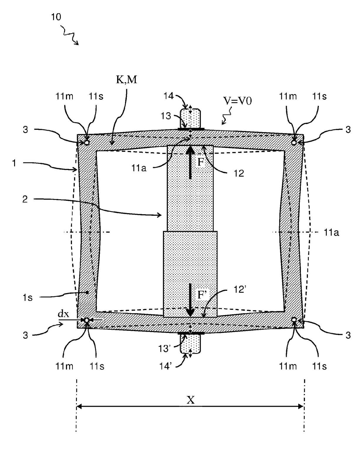
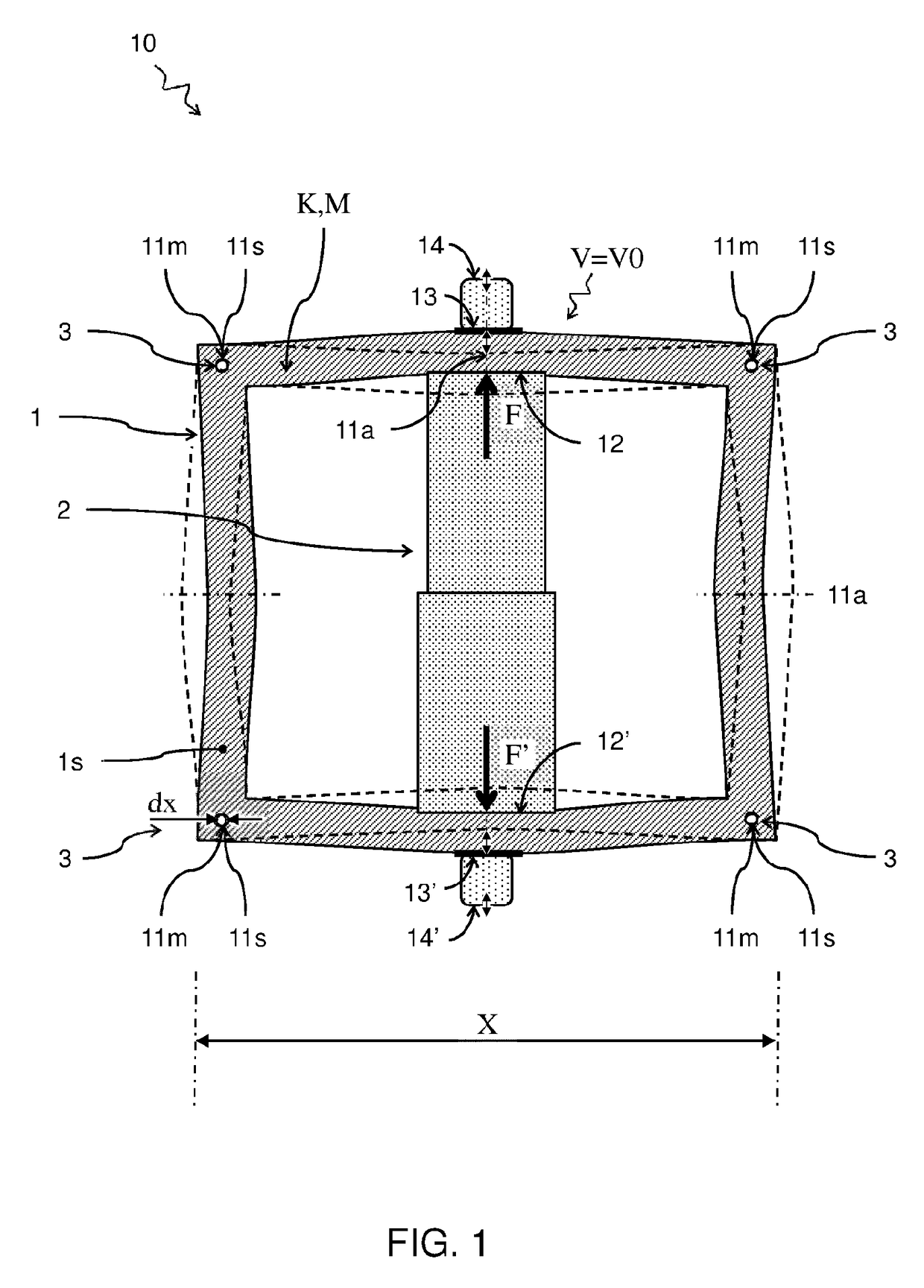
[0008]It is presently recognized that by adapting the actuator module such that the static nodal points coincide with the mode nodal points, a frequency dependence of a position of the nodal points is reduced. For example, a position of the static nodal points can be adapted by a choice of the force distribution of the actuator on the frame and / or the stiffness distribution of the frame. Furthermore, a position of the mode nodal points can be adapted by a choice of the mass distribution of the frame and / or the stiffness distribution of the frame. Accordingly, one or more of the force distribution, stiffness distribution, and mass distribution can be adapted to have the static nodal points coincide with the mode nodal points. Finally, by connecting a base frame to the actuator module at the positions of the coinciding nodal points, a transfer of vibrations from the actuator module to the base frame is reduced. In particular, a frequency dependence of the transfer is reduced resulting in a more smooth dynamic transfer function or frequency response function.
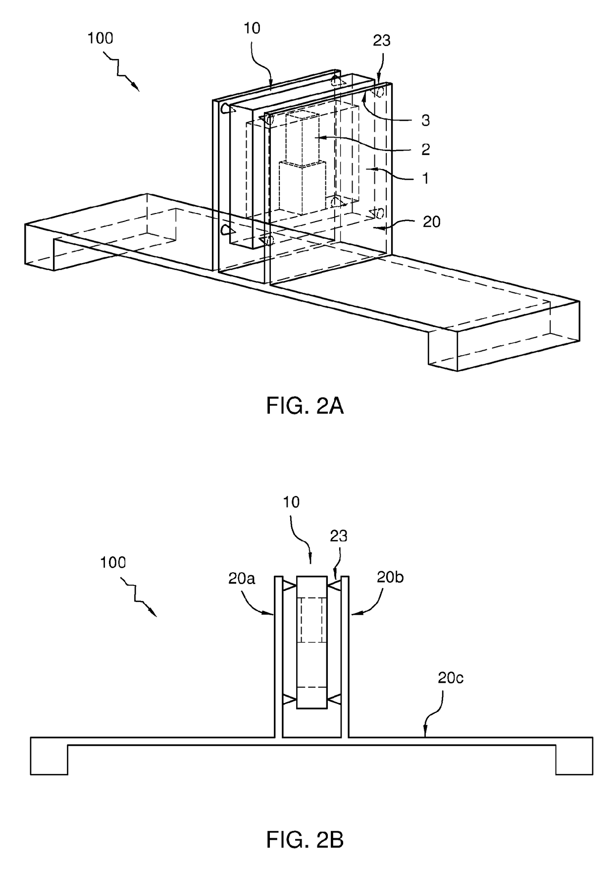
[0010]By providing the deformable frame with a plurality of frame connectors, the actuator module can be more easily connected to a base frame. By arranging the frame connectors at the interface of the deformable frame centred on the coinciding nodal points, vibrations in the module caused by the actuator may have minimal influence on the frame connectors, e.g. the forces on the frame connectors as a result of the combined static and modal transformations may be minimal. For example, a frame connector comprises a respective recess and / or protrusion centred on the coinciding nodal points. In this way the position of the nodal points can be easily identified and the deformable frame can be held via the recess and / or protrusion, e.g. by a corresponding structure on the base frame that mates with the respective recess and / or protrusion. By providing connections between the actuator module and base frame that are rotationally free around respective coinciding nodal points, twisting of the frame around said points that may occur during modal and / or static deformation is not passed to the base frame. By providing at least three connection points between the actuator module and base frame, the position may be advantageously determined.
[0011]As discussed above, during modal deformation, some parts of the deformable frame may remain stationary, i.e. the mode nodal points. On the contrary, other parts of the deformable frame between the mode nodal points, may exhibit maximal modal deformation. These are referred to as mode anti-nodes. It is found that by centring the connection between the actuator and deformable frame on a mode anti-node of the deformable frame, the static nodal points and mode nodal points can be more easily made to coincide. It will be appreciated that by exerting force where modal deformation is maximal a stronger coupling to the corresponding eigenmode may be established.
[0013]By providing the deformable frame with a mirror symmetric structure, it can be easier to identify the nodal points. For example where one nodal point appears on one side of the mirror plane, another can be expected at the other side. By applying, an equal but opposite force distribution on either side of the mirror symmetric structure the force distributions may result in an equal but opposite deformation of the mirror symmetric structure. For example, the force can be exerted by placing one or more actuators in between the mirroring sides. Symmetry can also be improved by providing an even number of actuators, e.g. two, working in opposite directions. For example when the two actuators are mirror symmetric with respect to each other, the symmetry in the system can be improved. The actuators can apply the same but oppositely oriented force distributions on either side of the deformable frame. It will be appreciated that improving symmetry of the system, can provide further benefit with regards to minimizing vibrational transfer to a base frame. In particular, in a symmetrically vibrating deformable frame, some points can remain stationary around the centre of mass of the frame.
[0014]An actuator system may comprise a base frame holding an actuator module as described herein. By minimizing the contact area on the deformable frame, the coinciding nodal points can be better targeted. For example, when the actuator module is connected to the base frame via a plurality of pins the contact area can be minimal.
[0016]It will be appreciated that the actuator module as described herein can provide benefit to systems that require good vibrational stability and control. For example, an atomic force microscopy system comprising a actuator module as described, can exhibit increased performance and predictability. The actuating surface can be arranged for actuating a probe tip for scanning a specimen surface in a controlled fashion with an as smooth as possible and predictable frequency response function.

Problems solved by technology

However, when the actuator module is connected to a base frame in a conventional way, movements of the actuator module may excite base frame vibrations.
These induced vibrations may influence the transfer or response function and deteriorate performance of the actuator system.

Method used


Image

  • Actuator module for actuating a load
  • Actuator module for actuating a load
  • Actuator module for actuating a load

Examples


Embodiment Construction

[0037]Unless otherwise defined, all terms (including technical and scientific terms) used herein have the same meaning as commonly understood by one of ordinary skill in the art to which this invention belongs as read in the context of the description and drawings. It will be further understood that terms, such as those defined in commonly used dictionaries, should be interpreted as having a meaning that is consistent with their meaning in the context of the relevant art and will not be interpreted in an idealized or overly formal sense unless expressly so defined herein. In some instances, detailed descriptions of well-known devices and methods may be omitted so as not to obscure the description of the present systems and methods. Terminology used for describing particular embodiments is not intended to be limiting of the invention. As used herein, the singular forms “a”, “an” and “the” are intended to include the plural forms as well, unless the context clearly indicates otherwise...


PUM


Abstract

The disclosure concerns an actuator module (10) for actuating a load (14). The actuator module (10) comprises a deformable frame (1) and an actuator (2) connected to the deformable frame (1). A time-varying force distribution (F) couples to an excited state (V0) of an eigenmode (V) of the deformable frame (1). The force distribution (F), as well as a stiffness distribution (K) and / or mass distribution (M) of the deformable frame 1 are adapted such that static nodal points (11s) of the deformable frame 1 are coincided with mode nodal points (11m). The locations where the nodal points coincide can be used to connect the actuator module (10) to a base frame to reduce transfer of vibrations to the base frame and back which may otherwise undesirably influence the transfer function from actuator to load. The disclosure further concerns a method for designing and / or manufacturing the actuator module.

Description

TECHNICAL FIELD AND BACKGROUND[0001]The present disclosure relates to an actuator module, actuator system comprising the actuator module, e.g. for use in an atomic force microscopy (AFM) system. The disclosure further relates to a computer-implemented method for designing an actuator module, a computer-readable storage medium, and a method for manufacturing an actuator module.[0002]An actuator module can be used to actuate a load, e.g. cause a vibrational motion of the load. For example in an atomic force microscope, an actuator module can be used as a scan head that actuates a probe tip for scanning a specimen surface.[0003]In general, it is desired that the dynamic transfer function or frequency response function between an applied actuator force (input) and a displacement of an actuating surface or probe (output) be as smooth as possible, e.g. free of disturbing resonances. However, when the actuator module is connected to a base frame in a conventional way, movements of the actu...

Claims


Application Information

Patent Timeline
Patent Type & Authority Patents(United States)
IPC IPC(8): G01Q10/04G01Q30/04G06F17/50G06F17/11
CPCG01Q10/04G06F17/5009G06F17/11G01Q30/04G06F30/20
Inventor WITVOET, GERRITVAN DEN DOOL, TEUNIS CORNELISCROWCOMBE, WILLIAM EDWARDDE LANGE, THEODORUS JACOBUSPEREBOOM, HAJO PIETER
Owner NEDERLANDSE ORG VOOR TOEGEPAST-NATUURWETENSCHAPPELIJK ONDERZOEK (TNO)
Why Eureka
Try Eureka