Broadband matching network

a wideband matching and network technology, applied in the direction of amplifier input/output impedence modification, amplifier modification to extend bandwidth, high-frequency amplifiers, etc., can solve the problem of low matching bandwidth of such planar matching networks, and achieve the effect of reducing the frequency dependence of load impedance and improving power transmission

Active Publication Date: 2019-11-05
COMET
View PDF14 Cites 0 Cited by
  • Summary
  • Abstract
  • Description
  • Claims
  • Application Information

AI Technical Summary

Benefits of technology

[0005]According to a first aspect a broadband matching network for coupling or connecting to an output of an amplifying device for an amplifier arrangement with a nominal operating frequency between 1 MHz and 100 MHz, more preferably between 5 MHz and 85 MHz and an output power of at least 100 W, more preferably at least 200 W and most preferably at least 250 W, is provided. The broadband matching network comprises a planar transformer with a primary winding arranged on a primary side of the broadband matching network and a secondary winding arranged on a secondary side of the broadband matching network. The primary winding is arranged to be electrically connected to the output of the amplifying device. The broadband matching network is characterized by a center frequency and a bandwidth with a frequency range of at least + / −3%, preferably at least + / −5%, more preferably at least + / −7% around the center frequency. The center frequency corresponds to the nominal operating frequency of the amplifier arrangement. The broadband matching network is arranged such that a series resonance frequency of the broadband matching network corresponds to the center frequency and a first parallel resonance frequency and a second parallel resonance frequency are arranged around the series resonance frequency such that a frequency dependence of a load impedance provided by the broadband matching network for the amplifying device is reduced.
[0036]The combination of the amplifying device and the broadband matching circuit may enable an improved amplifier arrangement which can be used to improve power transfer especially in case of connection to a time varying or dynamic external load as described above. The amplifying device may preferably be a push-pull amplifier as described above and below.

Problems solved by technology

The matching bandwidth of such planar matching networks is usually low.

Method used


Image

  • Broadband matching network
  • Broadband matching network
  • Broadband matching network

Examples


Embodiment Construction

[0063]Various embodiments of the invention will now be described by means of the Figures.

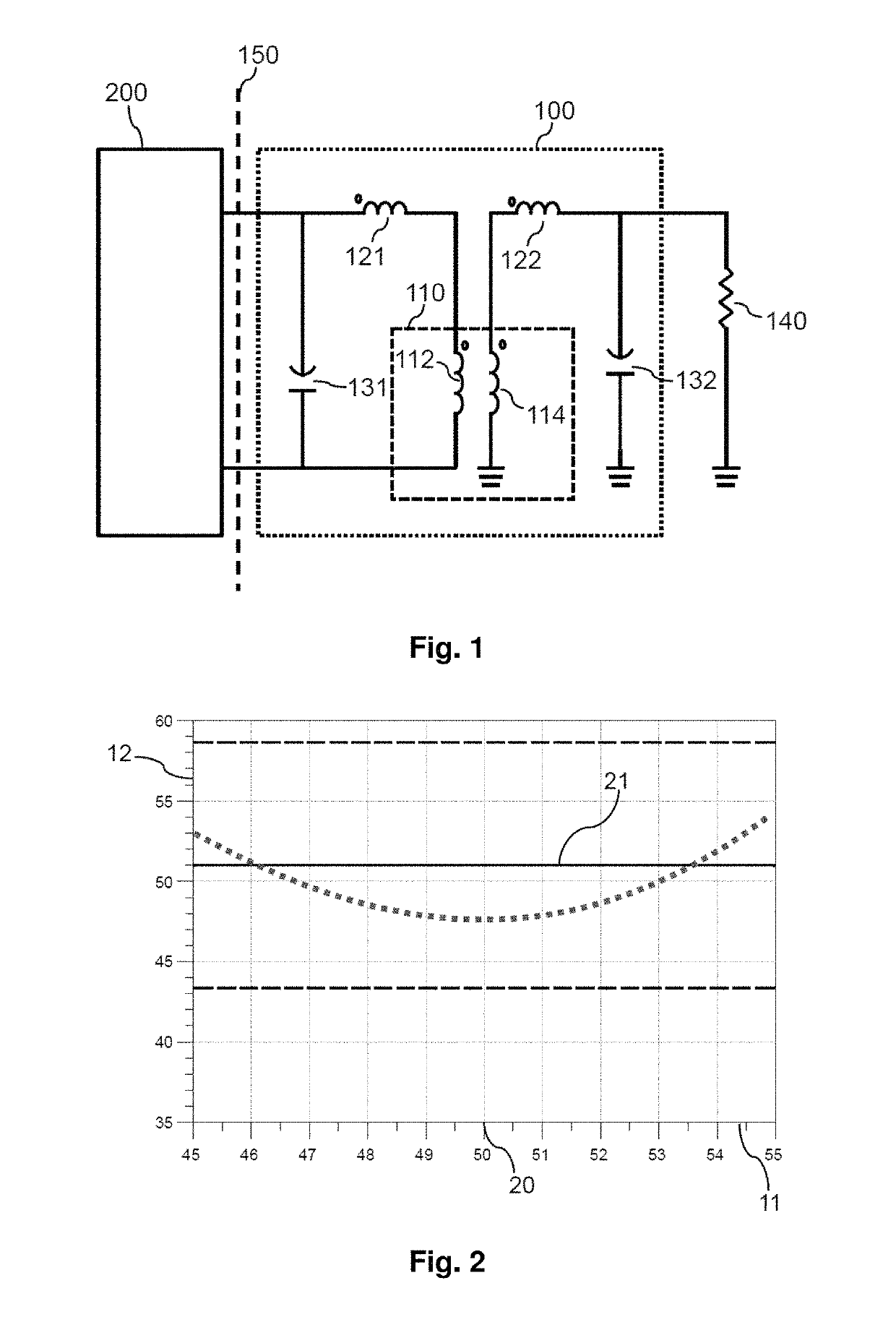
[0064]FIG. 1 shows a schematic drawing of a first broadband matching network 100 in combination with a schematic drawing of an amplifying device 200 connected at a reference plane 150 to an input of the broadband matching network 100 and an external load 140 which is connected to an output of the broadband matching network 100. The broadband matching network 100 comprises in this symmetric embodiment a first shunt capacitance 131 and a first serial inductor 121 on the primary side of the planar transformer 110. The planar transformer 110 comprises a primary winding 112 on the primary side. The broadband matching network 100 further comprises a second shunt capacitor 132 and a second serial inductor 122 on the secondary side of the planar transformer 110. The planar transformer 110 further comprises a secondary winding 114 on the secondary side. The first broadband matching network 100 is charact...


PUM


Abstract

The invention describes a broadband matching network for coupling to an output of an amplifying device for amplifiers with a nominal operating frequency between 1 MHz and 100 MHz. The broadband matching network comprises a planar transformer with a primary winding arranged on a primary side of the broadband matching network and a secondary winding arranged on a secondary side of the broadband matching network. The primary winding is arranged to be electrically connected to the output of the amplifying device. The broadband matching network is characterized by a center frequency and a bandwidth with a frequency range of at least + / −3%. A first parallel resonance frequency and a second parallel resonance frequency of the broadband matching circuit are arranged around the series resonance frequency such that a frequency dependence of a load impedance provided by the broadband matching network for the amplifying device is reduced.

Description

RELATED APPLICATIONS[0001]The present invention claims priority of EP 16181040.3, filed on 25 Jul. 2016, the entirety of which is incorporated herein by reference.FIELD OF THE INVENTION[0002]The invention relates to a broadband matching network for an amplifying device, an amplifier arrangement comprising such a broadband matching network, an electrical generator comprising such an amplifier arrangement and a plasma processing system comprising such an electrical generator. The invention further relates to a method of implementing a broadband matching network for an amplifier arrangement.BACKGROUND OF THE INVENTION[0003]Matching networks are used in order to transform the impedance provided by the load of an amplifier, e.g. a plasma processing system, to a proper load impedance at a reference plane of the amplifying device, e.g. a transistor. Especially matching networks which can be integrated on a printed circuit board (PCB) are interesting in order to enable cost-effective constr...

Claims


Application Information

Patent Timeline
Patent Type & Authority Patents(United States)
IPC IPC(8): H03F1/56H03F3/19H03F3/21
CPCH03F1/565H03F3/21H03F3/19H03F2200/387H03F2200/451H03H7/38H03F2200/36H03F2200/541H03F1/42H03F3/265H03F3/193
Inventor LABANC, ANTONGRUNER, DANIELREIFF, MARKUS
Owner COMET
Why Eureka
Try Eureka