Eureka AIR delivers breakthrough ideas for toughest innovation challenges, trusted by R&D personnel around the world.

Scissor forceps

Inactive Publication Date: 2019-07-04
OLYMPUS CORP
View PDF0 Cites 0 Cited by
  • Summary
  • Abstract
  • Description
  • Claims
  • Application Information

AI Technical Summary

Benefits of technology

The invention is a pair of scissor forceps that always generate a biasing force when the blades are closed, which pushes them together and makes sure they are always in perfect contact with each other. This ensures that the cutting target is always secure and free from getting stuck between the blades. The forceps also use a pulley system to make the blades move smoothly with minimal effort. Additionally, the technology allows for effective cutting through emission of energy by the energy emitting portion. Overall, the technology improves the cutting performance of the forceps.

Problems solved by technology

Therefore, there is inconvenience that the biasing force is not generated and a gap between the blade surfaces is made around the roots of the blades, at which the blade surfaces begin to get contact with each other first, and a cutting target gets stuck between the blade surfaces and becomes impossible to cut.

Method used


Image

  • Scissor forceps
  • Scissor forceps
  • Scissor forceps

Examples


Embodiment Construction

[0005]The disclosed technology is made in view of the circumstances described hereinbefore and intends to provide one or more scissor forceps that can always generate a biasing force that presses blade surfaces of a pair of blades against each other when the blades are closed, and can cut a cutting target more surely.

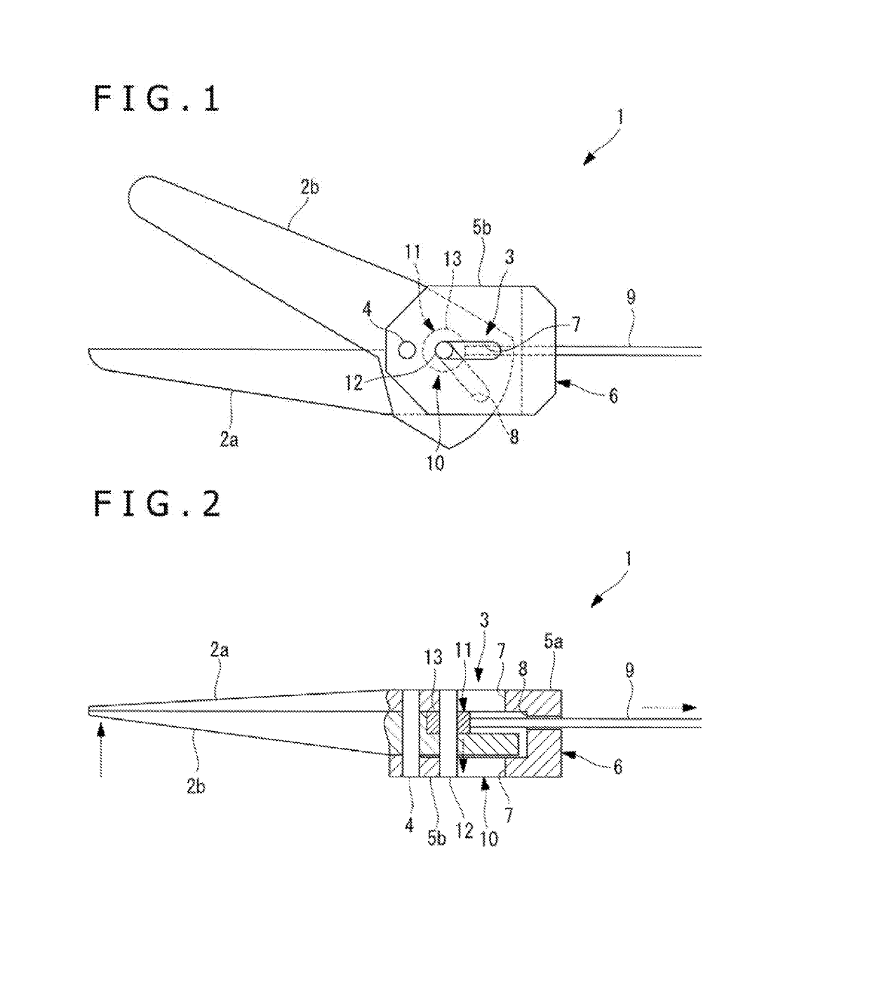
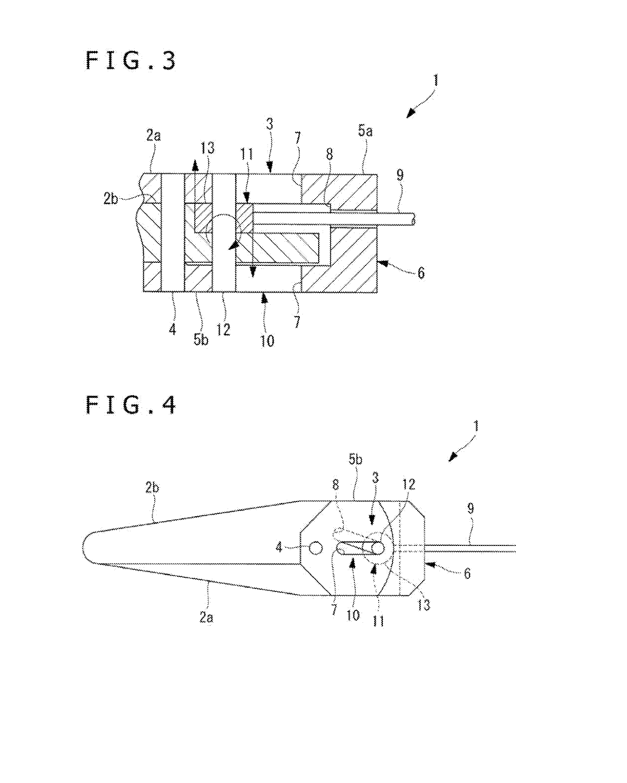
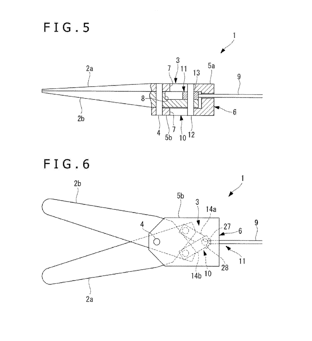
[0006]One aspect of the disclosed technology is directed to a scissor forceps including a base, a pair of blades that are attached relatively pivotally around a swing shaft attached to the base in the state of being disposed to be overlapping in the direction of the swing shaft and are restricted from moving in the direction along the swing shaft at the position of the swing shaft, and a drive mechanism that being used to drive the blades. The drive mechanism includes a power transmitting member that transmits a pulling force, a swing mechanism that is disposed on the proximal side of the blades relative to the swing shaft and converts part of the pulling force transmit...


PUM


Abstract

A scissor forceps comprises a base and a pair of blades configured to be pivotally attached to one another via a swing shaft attached to the base in an overlapping relationship. A drive mechanism is used to drive the blades and includes a power transmitting member that transmits a pulling force. A swing mechanism is disposed on a proximal side of the blades relative to the swing shaft converting a portion of the pulling force being transmitted by the power transmitting member to a first force that swings the blades. A pressing mechanism that converts another portion of the pulling force to a second force that separates the blades in the axial direction of the swing shaft on the proximal side of the blades. The swing mechanism includes cam grooves formed through the blades along directions that intersect one another on the proximal side of each of the blades.

Description

CROSS-REFERENCE TO RELATED APPLICATION[0001]This application is a continuation application of PCT Application No. PCT / JP2016 / 084388 filed on Nov. 21, 2016, which is hereby incorporated by reference in its entirety.TECHNICAL FIELD[0002]The disclosed technology relates to one or more scissor forceps.DESCRIPTION OF THE RELATED ART[0003]Conventionally, a scissor forceps are known in which a slope is made at part of a link mechanism for opening and closing a pair of blades that are pivotally coupled and blade surfaces of both blades are biased in such a direction as to be pressed against each other when the pair of blades are closed. For example, refer to PTL 1 or Japanese Patent Laid-open No. 2012-165812[0004]However, in the scissor forceps of PTL 1, a link gets on the slope made in the other link, and thereby a biasing force that presses the blade surfaces of both blades against each other is generated. Therefore, there is inconvenience that the biasing force is not generated and a gap...

Claims


Application Information

Patent Timeline
IPC IPC(8): A61B17/3201B26B17/00A61B17/28
CPCA61B17/3201B26B17/00A61B17/28A61B2018/00601A61B18/00
Inventor NAKAMURA, TAKASHI
Owner OLYMPUS CORP
Why Eureka
Eureka Blog
Learn More