Knife structure allowing rapid and safe replacement, and secure positioning, of blade, and knife handle structure thereof

Active Publication Date: 2019-07-18
KANTAS PROD
View PDF0 Cites 7 Cited by
  • Summary
  • Abstract
  • Description
  • Claims
  • Application Information

AI Technical Summary

Benefits of technology

[0006]One objective of the present invention is to provide a knife structure that allows its blade to be rapidly and safely replaced and securely positioned. The knife structure includes, sequentially in a top-to-bottom direction, a blade, an engaging and pushing plate, and an engaging and positioning base. A first connecting member is fixed to the engaging and pushing plate and is movably engaged in the blade and the engaging and positioning base. An engaging block is fixed to the engaging and positioning base and is movably engaged in the blade and the engaging and pushing plate. Once the blade, the engaging and pushing plate, and the engaging and positioning base are put together, the first connecting m

Problems solved by technology

To meet different cutting needs, therefore, one may have to carry several knives with them at the same time, but this will increase the purchase cost incurred by the user and the trouble the user must undergo while carrying the knives around or performing maintenance work on the knives.
While such a knife structure does allow its user to purchase different blades (e.g., those with a plain edge, a partly serrated or combo edge, or a fully serrated edge) as needed, and mount whichever blade that is called for by the situation at hand to the handle, the applicant has found a common drawback among those knife structures: a user trying to mount or replace a blade not only is required to use both hands, but also must grip a portion of the blade that is close to the front end (i

Method used


Image

  • Knife structure allowing rapid and safe replacement, and secure positioning, of blade, and knife handle structure thereof
  • Knife structure allowing rapid and safe replacement, and secure positioning, of blade, and knife handle structure thereof
  • Knife structure allowing rapid and safe replacement, and secure positioning, of blade, and knife handle structure thereof

Examples


Example

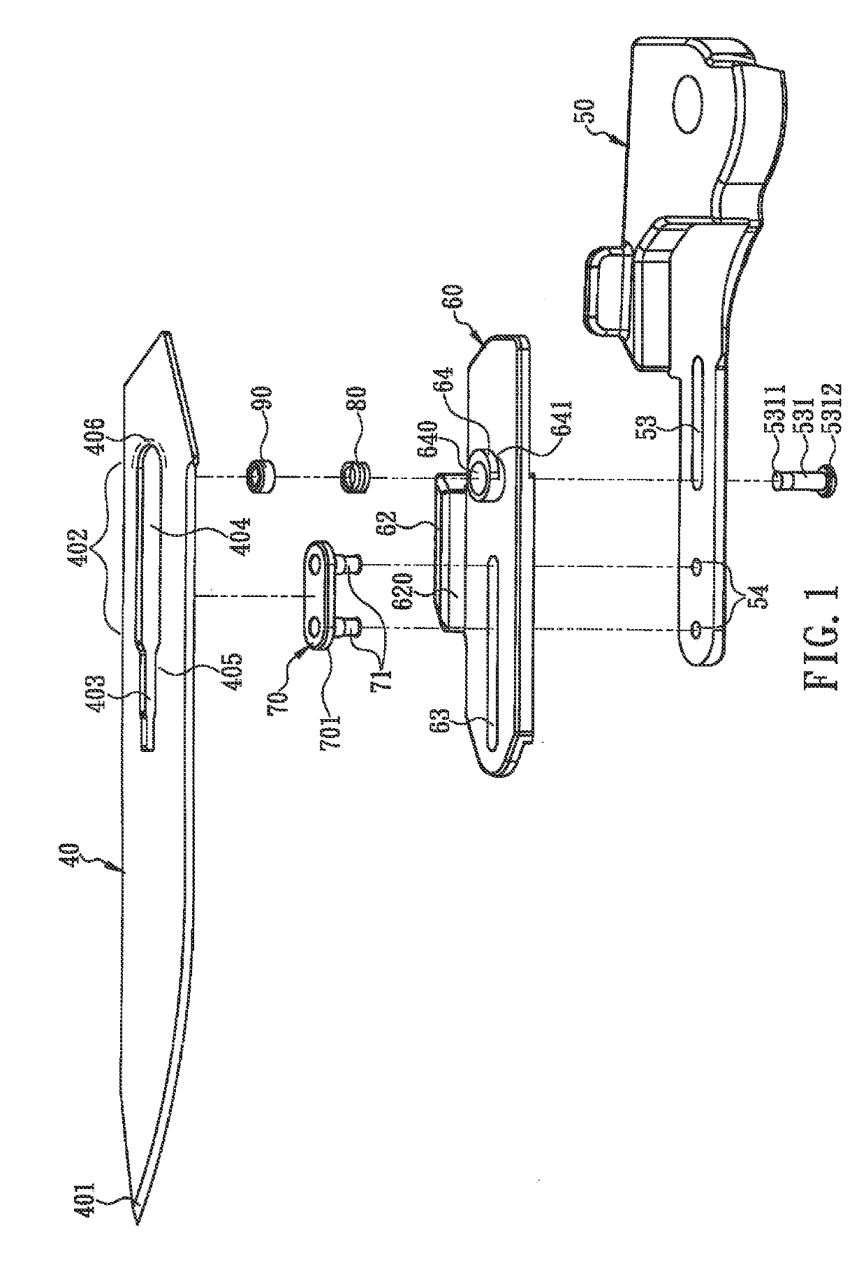
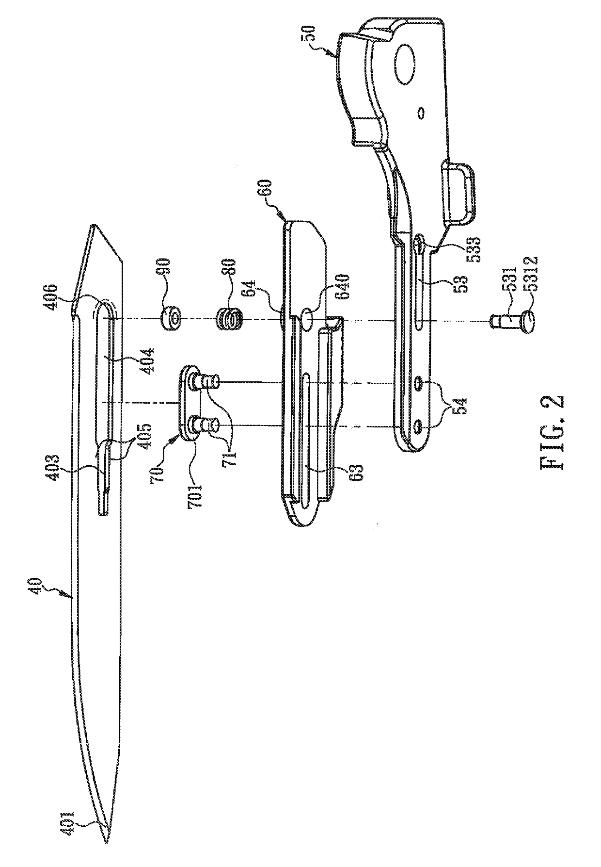
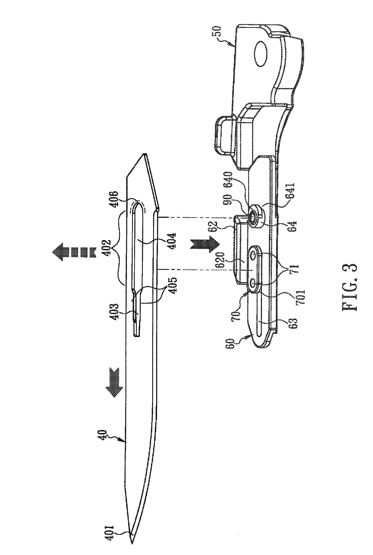
[0016]The present invention discloses a knife structure that allows its blade to he rapidly and safely replaced and securely positioned. Also disclosed is the knife handle structure of the knife structure. Referring to FIG. 1 for an exploded top perspective view of the knife structure according to a preferred embodiment of the invention, the knife structure includes a blade 40, an engaging and positioning base 50, an engaging and pushing plate 60, an engaging block 70, a pushing and unlocking key 90, and an elastic element 80. The front end of the blade 40 forms a blade tip 401. The spine of the blade 40 is formed with a first abutting edge 402 adjacent to the rear end of the blade 40. The blade 40 is formed with a first engaging hole 403 and a second engaging hole 404, which are adjacent to the rear end of the blade 40 and are sequentially arranged along the longitudinal direction of the blade 40. The engaging holes 403 and 404 are elongated in shape and are connected to, and there...


PUM


Abstract

A knife structure allowing rapid and safe replacement, and secure positioning of, a blade disposed along with its handle structure; wherein the knife structure includes the blade, an engaging and pushing plate, and an engaging and positioning base; a first connecting member is fixed to the engaging and pushing plate and is movably engaged in the blade and the engaging and positioning base; an engaging block is fixed to the engaging and positioning base and is movably engaged in the blade and the engaging and pushing plate; and the first connecting member is locked to the engaging and positioning base upon assembly of the knife structure. Once unlocked via a pushing and unlocking key, the first connecting member can be used to push the engaging and pushing plate and the blade simultaneously, allowing the blade to be pushed out of engagement with the engaging block and then detached for replacement.

Description

FIELD OF THE INVENTION[0001]The present invention relates to knifes and more particularly to a knife structure in which a blade can be rapidly detached for replacement by first pressing a pushing and unlocking key to disengage an engaging and pushing plate, on which the blade is provided, from an engaging and positioning base, and then pushing the blade out of engagement with the engaging block on the engaging and pushing plate.BACKGROUND OF THE INVENTION[0002]Different types of cutting edges have their respective pros and cons. To meet different cutting needs, therefore, one may have to carry several knives with them at the same time, but this will increase the purchase cost incurred by the user and the trouble the user must undergo while carrying the knives around or performing maintenance work on the knives. As a solution, the concept of “replaceable” structures has been applied to common knife products, resulting in knife structures with replaceable blades.[0003]While such a kni...

Claims


Application Information

Patent Timeline
IPC IPC(8): B26B5/00
CPCB26B5/00B26B1/044
Inventor CHENG, YANG-FU
Owner KANTAS PROD
Why Eureka
Try Eureka