Interactive virtual display
What is Al technical title?
Al technical title is built by PatSnap Al team. It summarizes the technical point description of the patent document.
a virtual display and interactive technology, applied in the field of interactive virtual displays, can solve the problem of how accurately it can work with a touch sensor
Active Publication Date: 2019-07-18
NEONODE
View PDF5 Cites 6 Cited by
Summary
Abstract
Description
Claims
Application Information
AI Technical Summary
This helps you quickly interpret patents by identifying the three key elements:
Problems solved by technology
Method used
Benefits of technology
The present invention provides a touch system with a curved surface that can detect and locate objects using light beams and reflected light. The system includes a housing, a curved surface, light emitters, light detectors, and a processor. The light beams emitted by the light emitters are incident on the curved surface and reflected by the object, which is detected by the light detectors. The processor synchronously activates the light emitter-detector pairs and calculates the location of the object based on the position of the light detectors. The system can detect and locate objects on both the curved surface and the flexible surface of the housing. The technical effects of the invention include improved accuracy and efficiency in touch detection and a more immersive user experience.
Problems solved by technology
One of the issues in the use of curved screens in commercial electronics is how accurately it can work with a touch sensor.
Method used
Image
Click on the blue label to locate the original text in one second.
Reading with bidirectional positioning of images and text.
Examples
Embodiment Construction
[0146]Throughout this description, the terms “source” and “emitter” are used to indicate the same light emitting elements, inter alia LEDs, VCSELs and lasers, and the terms “sensor” and “detector” are used to indicate the same light detecting elements, inter alia photo diodes.
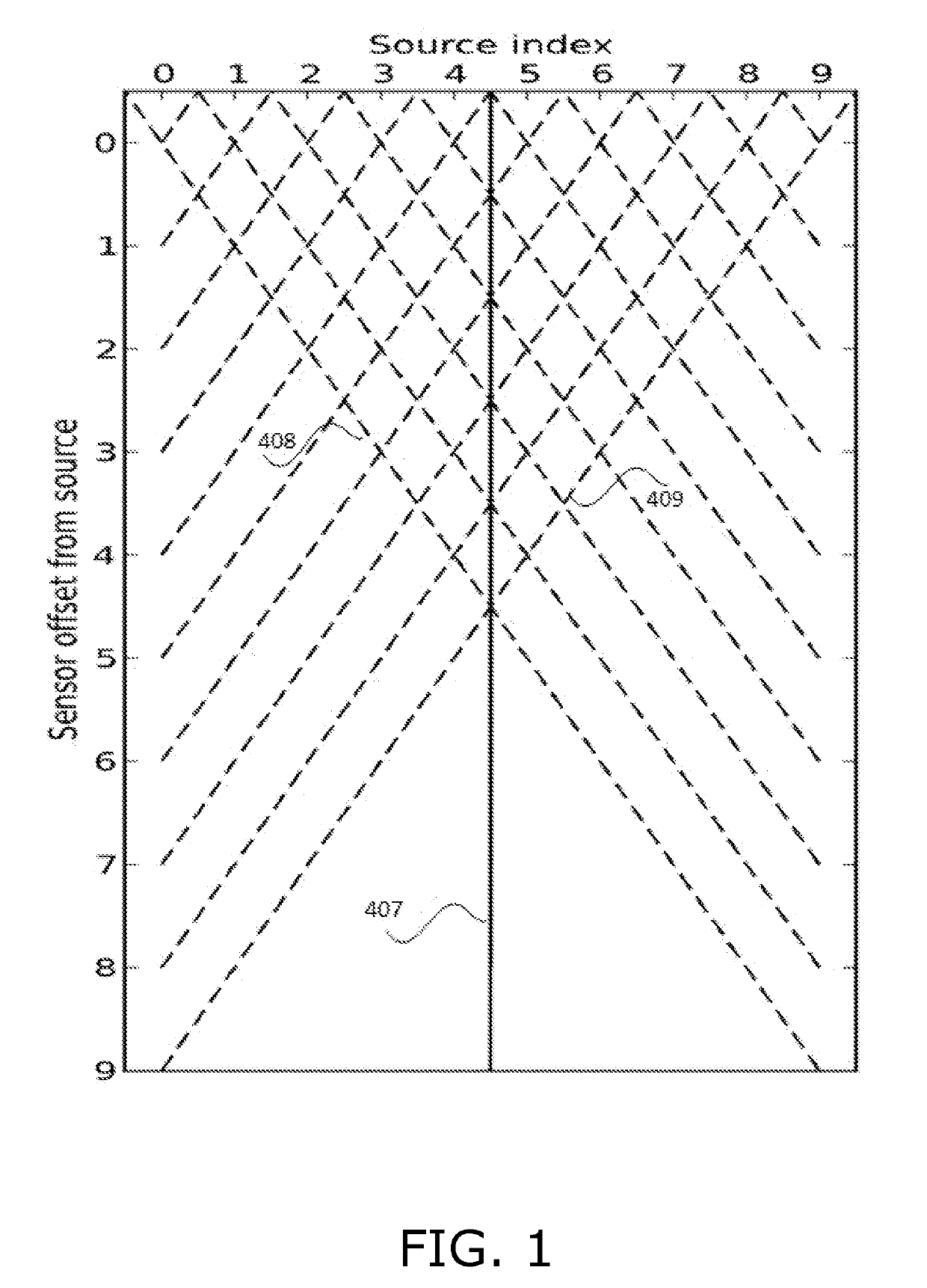
[0147]Reference is made to FIG. 1, which is a simplified illustration of light being emitted from light sources along a solid line, and being reflected along dashed lines to light sensors, in accordance with an embodiment of the present invention. FIG. 1 shows a central beam 407, and reflection paths 408, 409 represented by the dashed lines to light sensors, in accordance with an embodiment of the present invention. All of the dashed lines in FIG. 1 represent paths of reflected light that are maximally detected as explained below. FIG. 1 shows how light is emitted in a collimated beam. Light that hits an object is reflected diffusely. Sensors detect maximum incoming light from reflections in two narrow corridor...
PUM
Abstract
A sensor including optics configured in accordance with a display that presents a GUI, the optics projecting the GUI above the display such that the GUI is visible in-air, a reflectance sensor including light emitters projecting light beams towards the projected GUI, light detectors detecting reflections of the beams by objects interacting with the projected GUI, and a lens maximizing detection of light at each detector for light entering the lens at a respective location along the lens at a specific angle θ, whereby for each emitter-detector pair, maximum detection of light projected by the emitter of the pair, reflected by an object and detected by the detector of the pair, corresponds to the object being at a specific 2D location in the projected GUI, and a processor mapping detections of light for emitter-detector pairs to their corresponding 2D locations, and translating the mapped locations to display coordinates.
Description
CROSS REFERENCES TO RELATED APPLICATIONS[0001]This application claims priority benefit of U.S. Provisional Patent Application No. 62 / 425,087, entitled OPTICAL PROXIMITY SENSOR AND ASSOCIATED USER INTERFACE, filed on Nov. 22, 2016 by inventors Thomas Eriksson, Alexander Jubner, Rozita Teymourzadeh, Stefan Holmgren, Lars Sparf and Bengt Henry Hjalmar Edlund.[0002]This application claims priority benefit of U.S. Provisional Patent Application No. 62 / 462,034, entitled 3D IMAGING WITH OPTICAL PROXIMITY SENSOR, filed on Feb. 22, 2017 by inventors Thomas Eriksson, Alexander Jubner, Rozita Teymourzadeh, Stefan Holmgren, Lars Sparf, Bengt Henry Hjalmar Edlund.[0003]This application is a continuation-in-part of U.S. patent application Ser. No. 14 / 960,369, entitled INTEGRATED LIGHT GUIDE AND TOUCH SCREEN FRAME AND MULTI-TOUCH DETERMINATION METHOD, filed on Dec. 5, 2015 by inventors Thomas Eriksson, Alexander Jubner, John Karlsson, Lars Sparf, Saska Lindfors and Robert Pettersson.[0004]U.S. pat...
Claims
Application Information
Patent Timeline
Application Date:The date an application was filed.
Publication Date:The date a patent or application was officially published.
First Publication Date:The earliest publication date of a patent with the same application number.
Issue Date:Publication date of the patent grant document.
PCT Entry Date:The Entry date of PCT National Phase.
Estimated Expiry Date:The statutory expiry date of a patent right according to the Patent Law, and it is the longest term of protection that the patent right can achieve without the termination of the patent right due to other reasons(Term extension factor has been taken into account ).
Invalid Date:Actual expiry date is based on effective date or publication date of legal transaction data of invalid patent.
Patent Type & Authority Applications(United States)