
Lighting device

a technology of light source and light source, which is applied in the direction of lighting apparatus, instruments, light sources, etc., can solve the problem of absence of any true dynamic aspect of the achieved luminous pattern

Active Publication Date: 2019-07-25
SIGNIFY HLDG BV
View PDF2 Cites 2 Cited by
  • Summary
  • Abstract
  • Description
  • Claims
  • Application Information

AI Technical Summary

Benefits of technology

The inventors of this patent have realized that current optical devices tend to have a static optical structure, which generates luminous displays. These displays can appear to change as a user moves, but they don't have any true dynamic aspect. The patent suggests that by adding a dynamic component to the structure or operation of the device, it can offer improved levels of interest and engagement for observers. This means that the lighting device can create a more dynamic and interesting display for users.

Problems solved by technology

Although the static optical structure may be configured in some cases such that an apparent brightness or shape of the circular patterns appears to change as a user moves, there remains an absence of any true dynamic aspect to the achieved luminous patterns.

Method used


Image

  • Lighting device
  • Lighting device
  • Lighting device

Examples


Embodiment Construction

[0078]It should be understood that the Figures are merely schematic and are not drawn to scale. It should also be understood that the same reference numerals are used throughout the Figures to indicate the same or similar parts.

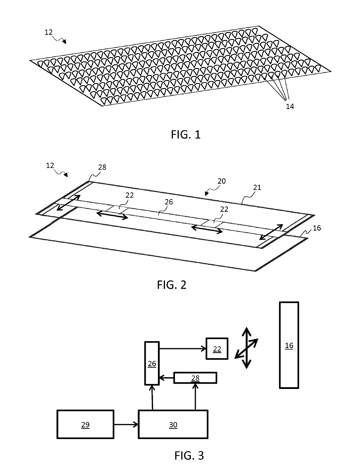
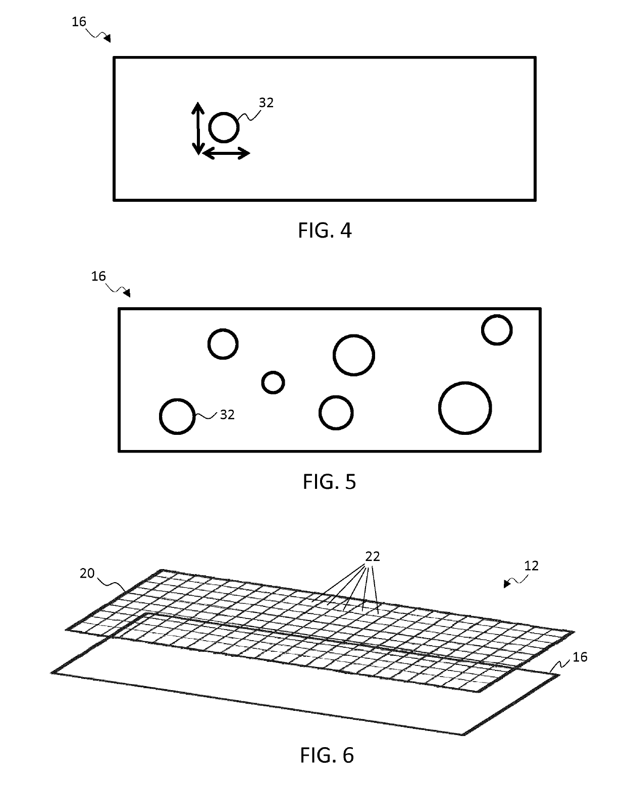
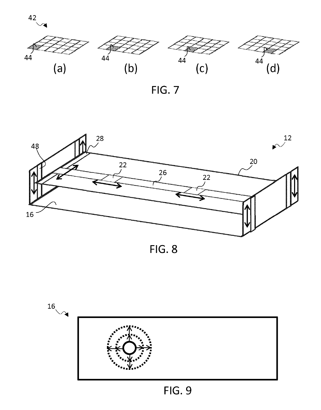
[0079]The invention provides a lighting device comprising an optical deglaring plate and a lighting assembly arranged in optical communication with the plate and comprising a plurality of light sources for projecting a plurality of luminous outputs onto an incident surface of the deglaring plate. The projected luminous outputs together generate a luminous pattern on the incident surface of the plate. The optical deglaring plate comprises an array of conical optical structures for optically processing the generated luminous pattern in order thereby to produce a corresponding lighting display on a reverse side of the plate. A controller is provided to control a configuration of the lighting assembly so as to vary the generated luminous pattern in dependence upo...


PUM


Abstract

A lighting device comprises an optical deglaring plate and a lighting assembly arranged in optical communication with the plate and comprising a plurality of light sources for projecting a plurality of luminous outputs onto an incident surface of the deglaring plate. The projected luminous outputs together generate a luminous pattern on the incident surface of the plate. The optical deglaring plate comprises an array of conical optical structures for optically processing the generated luminous pattern in order thereby to produce a corresponding lighting display on a reverse side of the plate. A controller is provided to control a configuration of the lighting assembly so as to vary the generated luminous pattern in dependence upon one or more variables, and thereby correspondingly vary the produced visible lighting display. The variables may, in particular examples, include a time variable and / or may include a tracked position of an observer relative to the device.

Description

FIELD OF THE INVENTION[0001]This invention relates to a lighting device, in particular to a lighting device for producing a lighting display on an optical deglaring plate.BACKGROUND OF THE INVENTION[0002]Decorative lighting devices, for providing ornamental luminous displays, are increasing in popularity. One known example of a decorative lighting device makes use of a so-called ‘conical deglaring plate’ which comprises a light transmissive array of cone-shaped structures, distributed on a supporting substrate. When spots of light are directed onto a surface of the deglaring plate, the spots are each transformed by the structure of the plate into a corresponding circular shaped light pattern visible on a reverse side of the plate.[0003]Known devices incorporating such plates typically utilise them to provide attractive luminous displays of circles and other closed curved forms. In some cases, the structure of the plate is configured such that an apparent brightness or shape of the c...

Claims


Application Information

Patent Timeline
Patent Type & Authority Applications(United States)
IPC IPC(8): H05B37/02G02B5/02
CPCH05B37/029H05B37/0227G02B5/0231H05B47/115H05B47/155Y02B20/40
Inventor HEEMSTRA, TEWE HIEPKE
Owner SIGNIFY HLDG BV
Learn More