
Negative mold comprising predefined foam blocks for casting a component and method for producing the negative mold

a technology of predefined foam blocks and molds, which is applied in the field of producing components, can solve the problems of rather complicated procedure of building up negative molds, and achieve the effect of easy work for workmen and very effective casting of components

Inactive Publication Date: 2016-05-24
SIEMENS GAMESA RENEWABLE ENERGY AS
View PDF20 Cites 5 Cited by
  • Summary
  • Abstract
  • Description
  • Claims
  • Application Information

AI Technical Summary

Benefits of technology

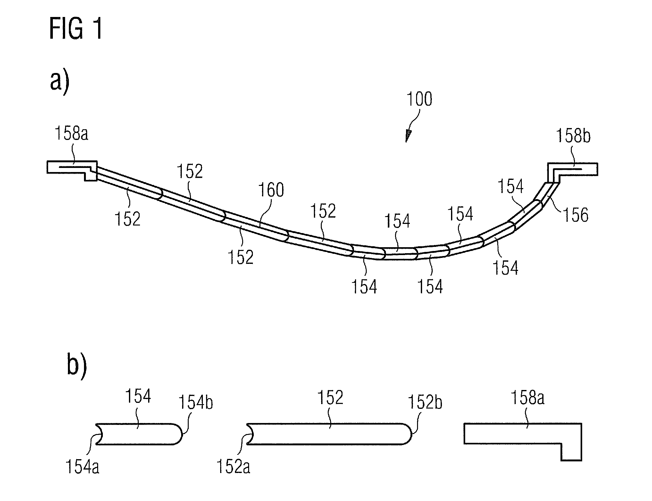
[0011]The described negative mold is based on the idea that for building up the negative mold it is not necessary to use individually shaped foam blocks, which are adapted to the geometry of the component, which is supposed to be casted. According to the invention the foam blocks are rather selected from a limited number of standardized foam block types, which are defined with respect to their geometry respectively with respect to their size and shape. This may provide the advantage that when building up the described negative mold one has to store only a limited number of different types of foam blocks which makes the casting of the component very effective.
[0043]In other words, the preordered arrangement of the foam blocks makes the work for a workman very easy. In particular an installation of appropriate foam pieces to the support structure and / or a trimming of the edges between different foam blocks can be carried out by using traditional handwork techniques.

Problems solved by technology

However, the disclosed negative mold has the disadvantage that building up the negative mold is a rather elaborate procedure.

Method used


Image

  • Negative mold comprising predefined foam blocks for casting a component and method for producing the negative mold
  • Negative mold comprising predefined foam blocks for casting a component and method for producing the negative mold
  • Negative mold comprising predefined foam blocks for casting a component and method for producing the negative mold

Examples


Embodiment Construction

[0050]The illustration in the drawing is schematically. It is noted that in different figures, similar or identical elements are provided with the same reference signs or with reference signs, which are different from the corresponding reference signs only within the first digit.

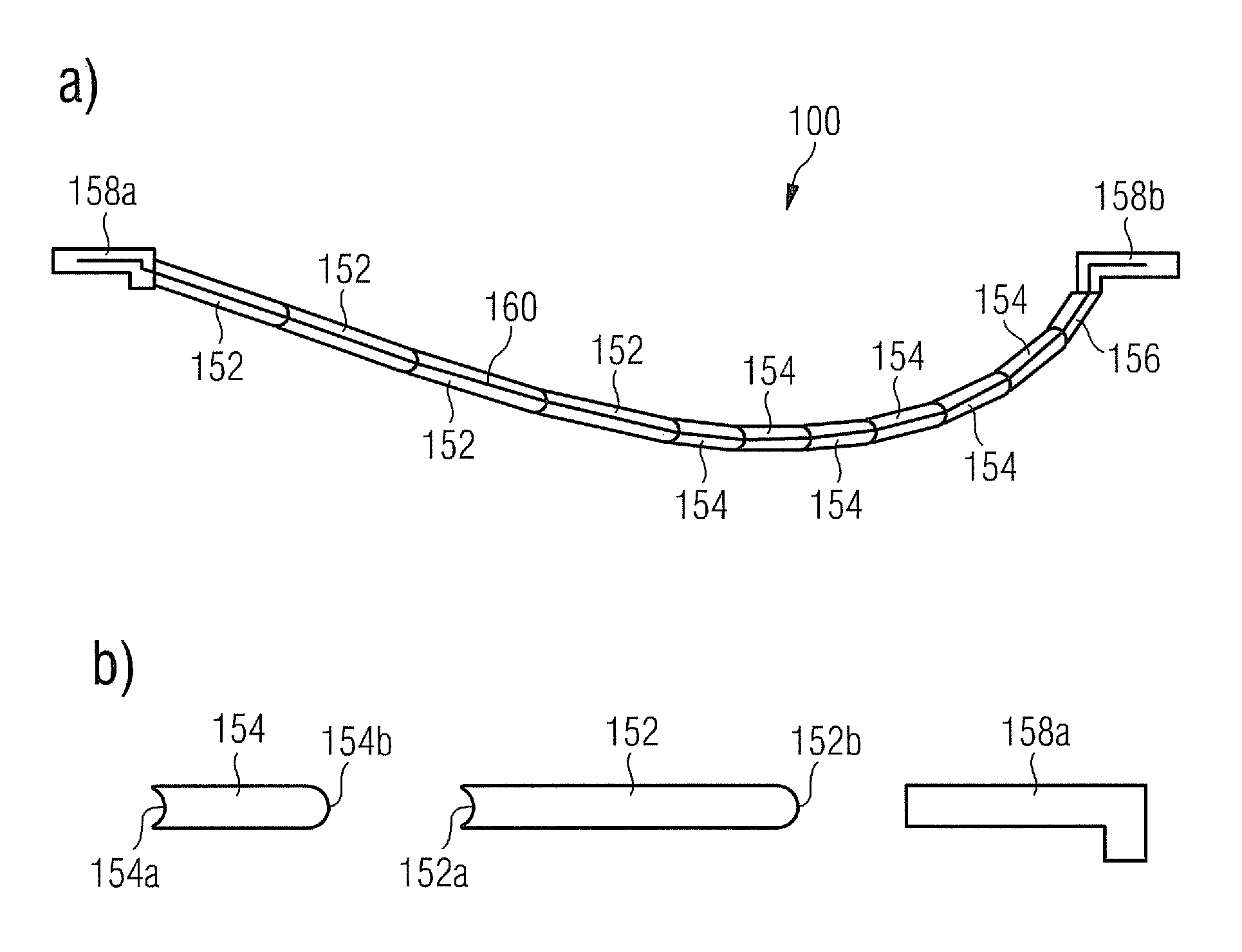
[0051]FIG. 1a shows in a cross sectional view a negative mold 100 for casting a wind turbine blade. The negative mold 100 has been built on a support structure or frame, which for the sake of clarity is not depicted in FIG. 1a. The negative mold 100 comprises a plurality of foam blocks. According to the embodiment described here each foam block is either a foam block 152 of a first type, a foam block 154 of a second type or a foam block of a third type 158a, 158b. In addition, the negative mold comprises a cut foam block 156, which has been produced by cutting off a portion of a foam block of the first type.

[0052]Compared to the inner foam blocks 152, 154b and 156 the outer foam blocks 158a, 158b have to sus...


PUM

PropertyMeasurementUnit
temperatureaaaaaaaaaa
densityaaaaaaaaaa
densityaaaaaaaaaa

Abstract

A negative mold for casting a component such as a blade of a wind turbine is described The negative mold includes a support structure and a plurality of foam blocks, which are mounted to the support structure in such a manner, that a common surface contour of the plurality of foam blocks defines an outer surface of the component, which is to be casted. Each foam block of the plurality of foam blocks is taken from a predetermined number of different types of foam blocks, each type of foam block is defined by a predetermined foam block size and foam block shape. A method for producing such a negative mold is also described.

Description

CROSS REFERENCE TO RELATED APPLICATIONS[0001]This application claims priority of European Patent Office application No. 10007254.5 EP filed Jul. 14, 2010, which is incorporated by reference herein in its entirety.FIELD OF INVENTION[0002]The present invention relates to the technical field of producing components by means of a casting procedure. The component may be a structural component of a wind turbine such as a blade of a wind turbine. In particular, the present invention relates to a negative mold for casting a component and to a method for producing a negative mold for casting a component.ART BACKGROUND[0003]A blade for a rotor of a wind turbine is typically produced by means of a casting procedure. The casting procedure for a new type of wind turbine blade comprises (a) producing a positive mold representing a design model of the blade which is supposed to be produced, (b) producing a negative mold representing negative copy of the positive mold and (c) producing the blade by...

Claims


Application Information

Patent Timeline
Patent Type & Authority Patents(United States)
IPC IPC(8): B29C33/40B28B7/36B29C33/38B29C33/30B29K105/04B29L31/08
CPCB29C33/3814B29C33/301B29K2105/04B29L2031/082B29C33/302B29K2023/12B29K2675/00B29L2031/085B29L2031/757
Inventor STEGE, JASON
Owner SIEMENS GAMESA RENEWABLE ENERGY AS
Learn More