Reusable adhesive mount device for portable electronics
- Summary
- Abstract
- Description
- Claims
- Application Information
AI Technical Summary
Benefits of technology
Problems solved by technology
Method used
Image

Examples
Embodiment Construction
[0045]While this invention is susceptible of embodiments in many different forms, there is shown in the drawings and will herein be described in detail preferred embodiments of the invention with the understanding that the present disclosure is to be considered as an exemplification of the principles of the invention and is not intended to limit the broad aspect of the invention to the embodiments illustrated.
[0046]The following table lists elements of the illustrated embodiments of the invention and their associated reference numbers for convenience.
REF. NO.—ELEMENT
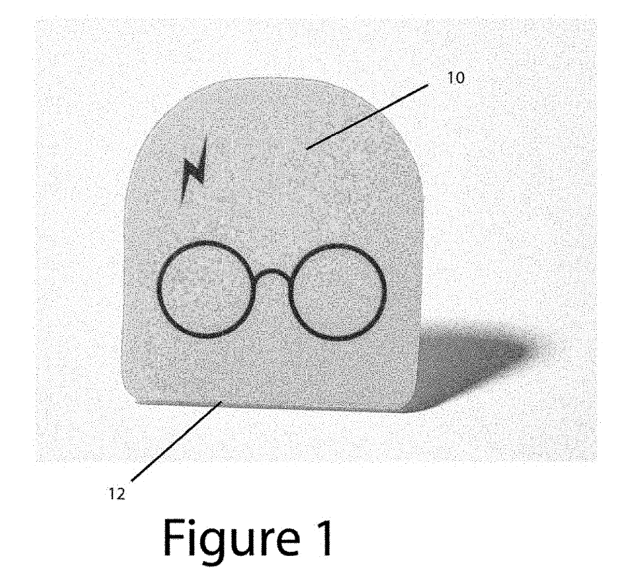
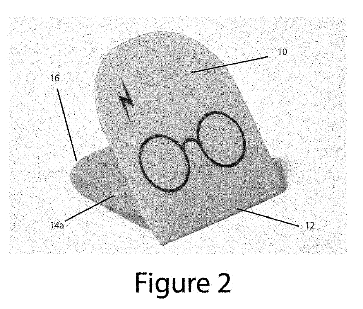
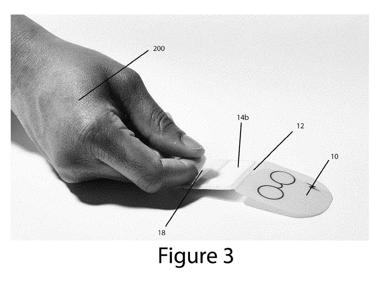
[0047]10—top-half of invention frame[0048]12—hinge[0049]14a—reusable adhesive front[0050]14b—reusable adhesive back[0051]16—bottom-half of invention frame[0052]18—protective film cover attached prior to use[0053]30—elastic band[0054]40a—front-half of sleeve[0055]40b—back-half of sleeve[0056]200—user hand[0057]210—smartphone[0058]220—credit cards
[0059]FIG. 1 shows the front-top of a reusable adhesive mount device in accor...
PUM
 Abstract
Description
Claims
Application Information
PatSnap Eureka turns technology decisions into work you can execute. Powered by our Innovation Knowledge Graph, it runs expert workflows across engineering, life sciences, materials and intellectual property. Get your review-ready output in minutes.


