Unmanned aerial vehicle provided with detachable motor arms

a technology motor arms, which is applied in the direction of aircrafts, fuselages, transportation and packaging, etc., can solve the problems of unmanned aerial vehicles (uavs) being at constant risk of hard landing, collisions, crashes, arm parts, propulsion systems,

Active Publication Date: 2019-08-29
PIKE JAMES THOMAS
View PDF0 Cites 10 Cited by
  • Summary
  • Abstract
  • Description
  • Claims
  • Application Information

AI Technical Summary

Benefits of technology

[0006]Implementations of an unmanned aerial vehicle (UAV) provided with detachable motor arms are provided. In this way, the UAV may be conveniently stored and transported, rapidly assembled in the field, and repaired in the event of a crash. In some implementations, the motor arms are configured to separate from the fuselage of the UAV upon crashing into the ground and / or another object. In this way, damage to the motors arms and / or the fuselage of the UAV may be minimized or prevented.
[0008]In some implementations, the mechanical connectors securing each motor arm to the fuselage of the UAV may be configured to facilitate the separation of the motor arm from the fuselage during a crash. In this way, damage to the motors arms and / or the fuselage of the UAV may be minimized or prevented. In some implementations, the mechanical connectors securing a motor arm to the fuselage of the UAV may be configured to separate from the fuselage during a crash. In some implementations, the mechanical connectors securing a motor arm to the fuselage of the UAV may be configured to release the motor arm if sufficient force (e.g., torque) is applied thereto in the correct direction.
[0010]In some implementations, the breakaway pegs of each mechanical connector are configured to be inserted and secured within cooperating sockets located in a side of the fuselage of the UAV. In this way, a motor arm may be secured to the fuselage of the UAV by a pair of mechanical connectors. In some implementations, the breakaway pegs are each configured to break (e.g., shaped and / or constructed from a suitable material) when sufficient force (e.g., torque) is applied thereto, such as during a crash. In this way, a motor arm secured by a pair of mechanical connectors to the fuselage can separate therefrom during a crash and thereby minimize or prevent damage to the fuselage and / or the motor arm.
[0012]In some implementations, the electrical connector of each motor arm may comprise registration sockets configured to receive registration pins extending from the underside of the fuselage. In this way, through the use of the registration pins, lateral movement of the electrical connector of a motor arm relative to the cooperating electrical connector in the underside of the fuselage is minimized or eliminated under normal flight conditions.
[0015]In some implementations, a flexible arm of a mechanical connector may include a groove therein that is configured (e.g., positioned) to weaken it. In this way, the portion of the mechanical connector weakened by the groove can break in the event of a crash.
[0016]In some implementations, prior to inserting the breakaway pegs into their cooperating sockets, the user may exert a transverse effort on the flexible arms of a mechanical connector in a direction that moves them closer together (i.e., the user may squeeze the flexible arms together). In this way, the breakaway pegs may be aligned with their cooperating sockets prior to insertion. In some implementations, once the breakaway pegs have been fully inserted into their cooperating sockets and the flexible arms released, the flexible arms, due to their elastically deformable nature, spring back into position (i.e., recover their shape) and thereby cause the breakaway pegs to engage with their respective sockets. In this way, each mechanical connector may be secured to the fuselage of a UAV.

Problems solved by technology

Unmanned aerial vehicles (UAVs) are at constant risk of hard landings, collisions, and crashes.
Often, an arm part, propulsion system, or the fuselage of a UAV is damaged during one of those events.

Method used


Image

  • Unmanned aerial vehicle provided with detachable motor arms
  • Unmanned aerial vehicle provided with detachable motor arms
  • Unmanned aerial vehicle provided with detachable motor arms

Examples


Embodiment Construction

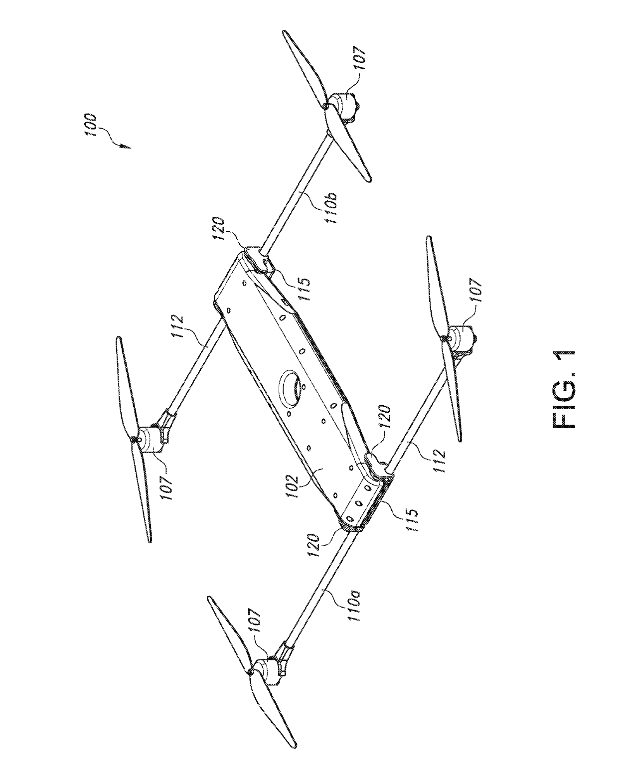
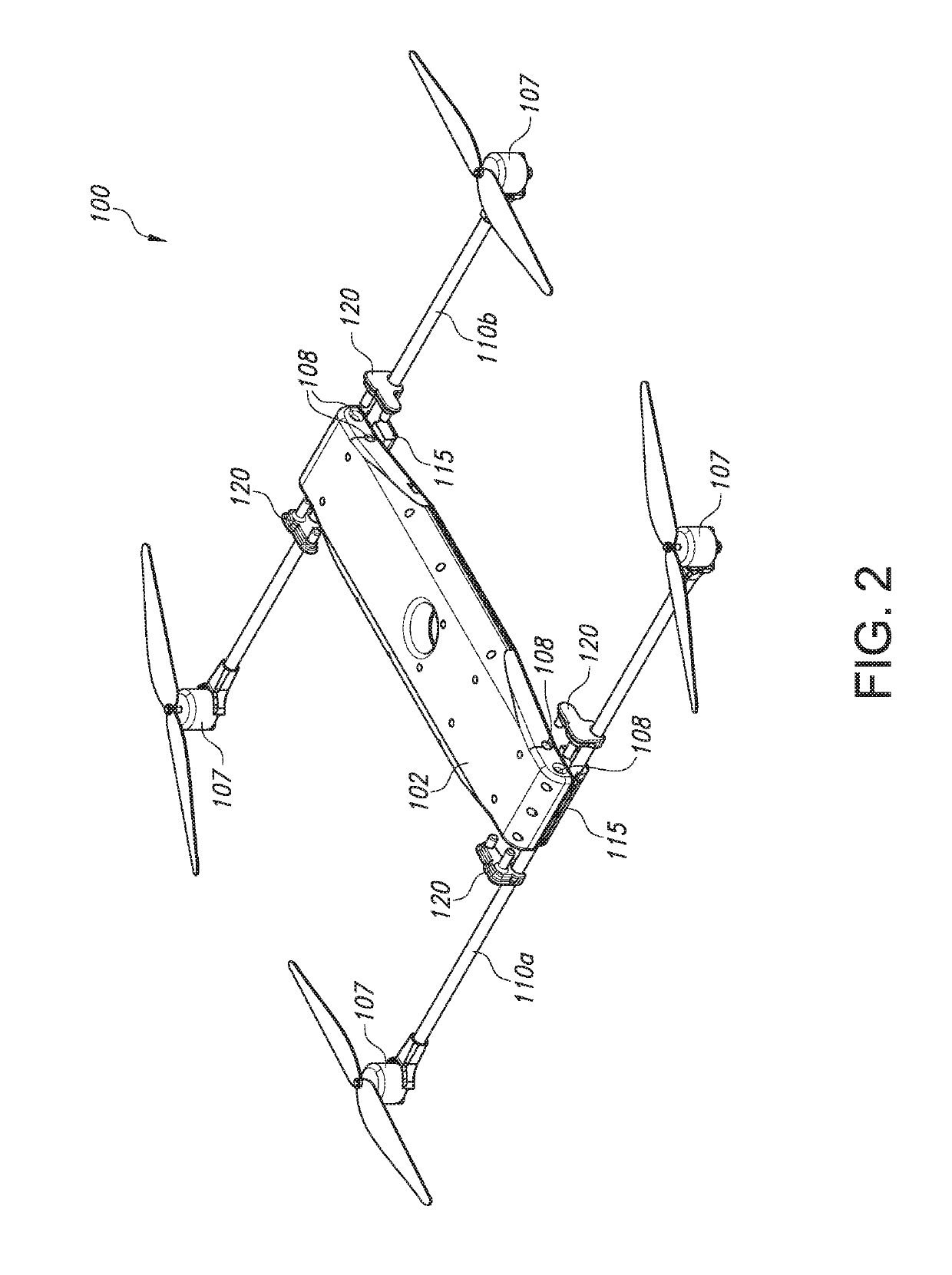
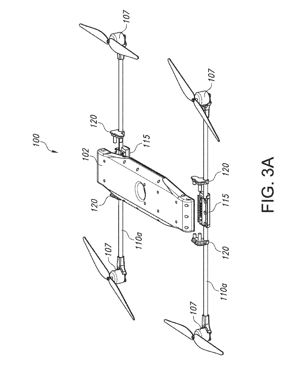
[0030]FIGS. 1-3A illustrate an example implementation of an unmanned aerial vehicle (UAV) 100 provided with detachable motor arms 110. In this way, the UAV 100 may be conveniently stored and transported, rapidly assembled in the field, and repaired in the event of a crash. In some implementations, the motor arms 110 may be configured to separate from the fuselage 102 of the UAV 100 upon crashing into the ground and / or another object. In this way, damage to the motors arms 110 and / or the fuselage 102 of the UAV 100 may be minimized or prevented.

[0031]As shown in FIGS. 1-3A, in some implementations, an example UAV 100 may comprise a fuselage 102 having a first motor arm 110a and a second motor arm 110b (collectively motor arms 110) detachably secured thereto, each motor arm 110a, 110b is detachably secured to the fuselage 102 by two mechanical connectors 120 (or fuses) and comprises a tube 112 having a rotary wing propulsion system 107 on each end thereof. In some implementations, e...


PUM


Abstract

Implementations of an unmanned aerial vehicle (UAV) provided with detachable motor arms are provided. In this way, the UAV may be conveniently stored and transported, rapidly assembled in the field, and repaired in the event of a crash. Also, the motor arms are configured to separate from the fuselage of the UAV upon crashing into the ground and / or another object. In this way, damage to the motors arms and / or the fuselage of the UAV may be minimized or prevented. An example UAV comprises a fuselage having two motor arms detachably secured thereto, each motor arm is detachably secured to the fuselage by two mechanical connectors (or fuses) and comprises a tube having a rotary wing propulsion system on each end thereof. The mechanical connectors securing each motor arm to the fuselage of the UAV are configured to facilitate the separation of the motor arm from the fuselage during a crash.

Description

CROSS REFERENCE TO RELATED APPLICATION[0001]This application claims the benefit of U.S. Provisional Application Ser. No. 62 / 635,335, which was filed on Feb. 26, 2018, the entirety of which is incorporated herein by reference.TECHNICAL FIELD[0002]This disclosure relates to implementations of an unmanned aerial vehicle (UAV) provided with detachable motor arms. In particular, the present invention is directed to implementations of a mechanical connector that can be used to secure a motor arm and / or a leg to the fuselage of a UAV.BACKGROUND[0003]An unmanned aerial vehicle (UAV), also known as a drone, is an aircraft without a human pilot aboard. UAV's are a component of an unmanned aircraft system (UAS) which includes a UAV and a ground-based controller that are connected by a two-way communication system. UAVs are often equipped with cameras, infrared devices, and other equipment according to its intended use, for example, surveillance, communication / information broadcasting, etc.[000...

Claims


Application Information

Patent Timeline
Patent Type & Authority Applications(United States)
IPC IPC(8): B64D27/26B64C27/08B64C25/32B64C39/02
CPCB64D27/26B64C27/08B64C25/32B64C39/024B64C2201/20B64C2201/024B64C2201/042B64C2201/108B64C2201/165B64C2025/325B64C1/062B64C2211/00B64U10/13B64U30/20B64U10/10B64U50/13B64U50/19B64U80/00
Inventor PIKE, JAMES THOMAS
Owner PIKE JAMES THOMAS
Why Eureka
Try Eureka