
Universal power interface system and methods to use the same

Active Publication Date: 2019-09-12
HARPER ENG
View PDF4 Cites 1 Cited by
  • Summary
  • Abstract
  • Description
  • Claims
  • Application Information

AI Technical Summary

Benefits of technology

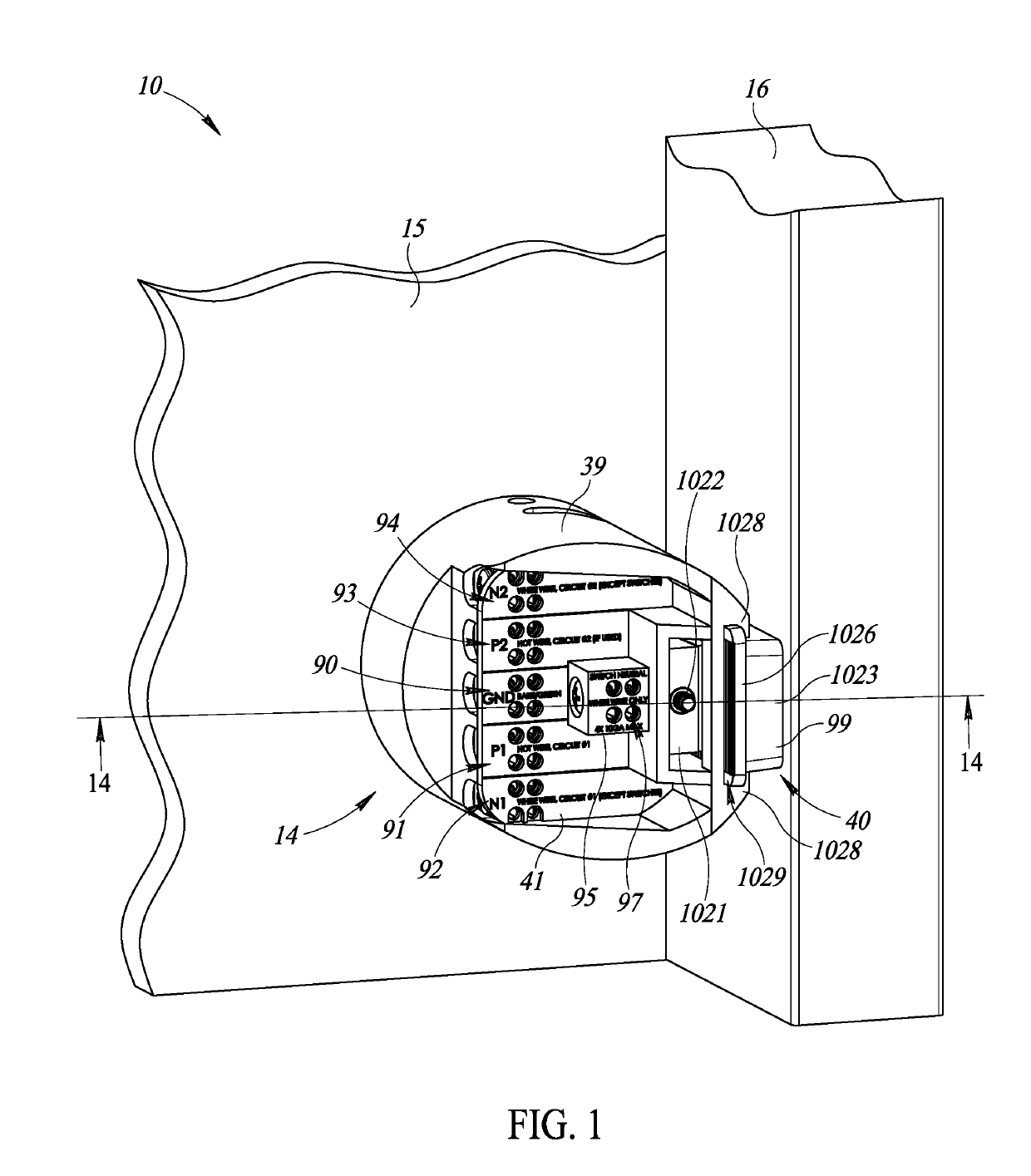
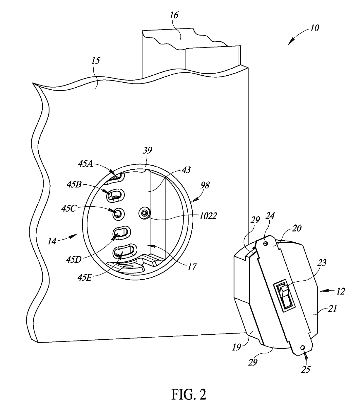
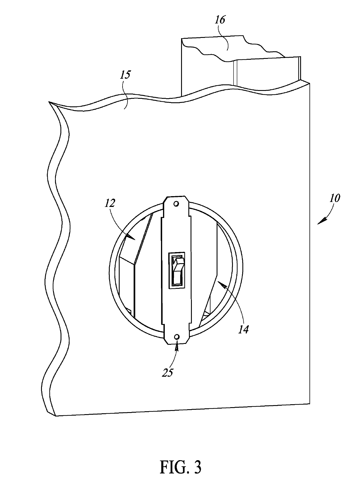
The patent describes a system that simplifies the installation of electrical devices by providing a power interface device with a receptacle region and a plurality of pin receiving apertures, and an electrical device module with a plurality of contact pins that can be coupled with the receptacle region. The electrical device module can be rotatably moveable between an uncoupled orientation and a coupled orientation, with the electrical device module being secured to the power interface device in the coupled orientation. The technical effect is to provide a system that allows for easy installation and uninstallation of various electrical devices.

Problems solved by technology

Replacing conventional electrical devices or installing new electrical devices can be time-consuming, complicated, labor-intensive, hazardous, and may require skilled labor.

Method used


Image

  • Universal power interface system and methods to use the same
  • Universal power interface system and methods to use the same
  • Universal power interface system and methods to use the same

Examples


Embodiment Construction

[0035]In the following description, certain specific details are set forth in order to provide a thorough understanding of various disclosed implementations or embodiments. One skilled in the relevant art will recognize that embodiments or implementations may be practiced without one or more of these specific details. In other instances, well-known structures and devices associated with electrical devices, building or housing structures, walls, ceilings, wiring, electrical junction or switch boxes, and related apparatuses, devices, and methods may not be shown or described in detail to avoid unnecessarily obscuring descriptions of the embodiments or implementations.

[0036]Unless the context requires otherwise, throughout the specification and claims which follow, the word “comprise” and variations thereof, such as, “comprises” and “comprising” are to be construed in an open, inclusive sense, that is, as “including, but not limited to.”

[0037]Reference throughout this specification to ...


PUM


Abstract

A power interface system is provided. The power interface system can include a power interface device coupleable to a structure, wherein the power interface device can include a receptacle region and a plurality of pin receiving apertures. The power interface system may include an electrical device module sized and shaped to be received in the receptacle region, the electrical device module having a plurality of contact pins, each of the plurality of contact pins sized and shaped to be coupleably received in one of the pin receiving apertures. The electrical device module can be rotatably moveable with respect to the receptacle region between an uncoupled orientation and a coupled orientation, with the electrical device module being secured to the power interface device in the coupled orientation. Related devices and methods are also provided.

Description

BACKGROUNDTechnical Field[0001]The present disclosure is related to universal power interface systems.Description of the Related Art[0002]Conventional electrical devices, such as power outlets, light switches, ceiling fans, light fixtures, etc. are generally hard-wired. For example, light switches are hard-wired to an electrical box disposed in a wall through which power is supplied. Similarly, power outlets are hard-wired to an electrical box disposed in a wall though which power is supplied. Likewise, other electrical devices, such as fans, light fixtures, etc., tend to be hard-wired in a similar manner.[0003]Conventional electrical devices, such as those described above, for example, over time become outdated and are desirable to be replaced with newer, technologically advanced, and aesthetically pleasing replacements. For example, in some instances, a conventional power outlet may be replaced with one that includes a conventional power outlet and a USB outlet. For example, a con...

Claims


Application Information

Patent Timeline
IPC IPC(8): H01R24/76H02G3/08H01R13/74H01R13/05H02G3/18
CPCH01R13/743H01R24/76H01R13/05H02G3/18H02G3/081H01R13/625H01R13/74H01R24/60H01R27/00H01R33/765H01R2107/00H02G3/12H02G3/20
Inventor CHADWELL, DAVID
Owner HARPER ENG
Learn More