Installation apparatus consisting of a wall plug and a holder which can be screwed therein for installing flush-mounted devices

Active Publication Date: 2021-04-29
OBLAMATIK AG
View PDF0 Cites 0 Cited by
  • Summary
  • Abstract
  • Description
  • Claims
  • Application Information

AI Technical Summary

Benefits of technology

[0026]In another embodiment, the pair of tightening elements forms a threaded connection or a bayonet socket connection. A threaded connection allows for the installation device to be drawn in smoothly, or the securing section to be deformed smoothly. This is advantageous if the installation conditions change or cannot be anticipated. The outer thread on the retainer can only extend over an edge region of the second end. Alternatively, it can extend one half, two thirds, three quarters, or more, of the distance to the flange. The threading on the retainer is longer than the threading on the wall plug. The internal thread on the wall plug should fundamentally extend more than at least twice the thread pitch, in order that the threading does not become stripped when tightening the retainer in the wall plug. Three, four, five, or more times the thread pitch is also an option.
[0027]A bayonet socket simplifies the installation when the installation conditions are constant and can be anticipated. The desired clamping force can thus be obtained in a lightweight wall through the design of the bayonet socket. This makes it impossible to tighten the installation device too much, such that the wall becomes damaged.
[0028]In order to reinforce the threaded region of the wall plug, the wall plug can be thicker in this region, or provided with a stronger material. By way of example, this can be obtained with a more sturdy plastic or a metal ring into which the thread is cut. Fewer thread windings are necessary to ensure that the thread does not become stripped when tightened if a metal ring is used. This makes it possible to shorten the wall plug.
[0029]There can be retaining elements on the outer surface of the wall plug, e.g. in the form of upright fins, which prevent the wall plug from slipping out of the recess in the wall. The upright fins also enlarge the contact region with the inner surface of the wall,

Problems solved by technology

Such outlet sockets take up a lot of

Method used


Image

  • Installation apparatus consisting of a wall plug and a holder which can be screwed therein for installing flush-mounted devices
  • Installation apparatus consisting of a wall plug and a holder which can be screwed therein for installing flush-mounted devices
  • Installation apparatus consisting of a wall plug and a holder which can be screwed therein for installing flush-mounted devices

Examples


Embodiment Construction

[0004]The object of the invention is to create a space-saving and easily installed installation device for installing flush-mounted fixtures.

[0005]This object is achieved by a device that has the features of claim 1. Further embodiments of the installation device, and installation system, and an installation method are defined by the features of the other claims.

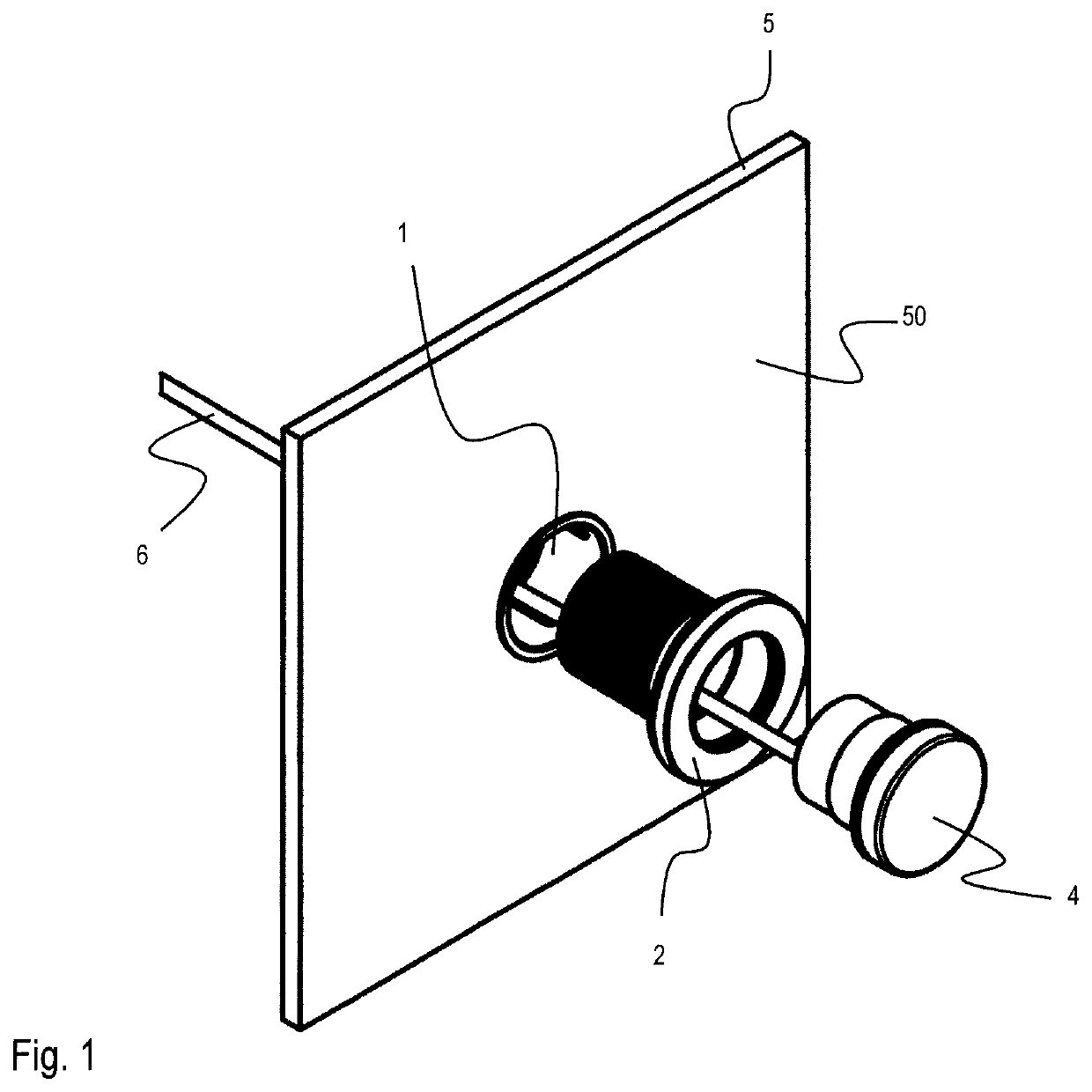
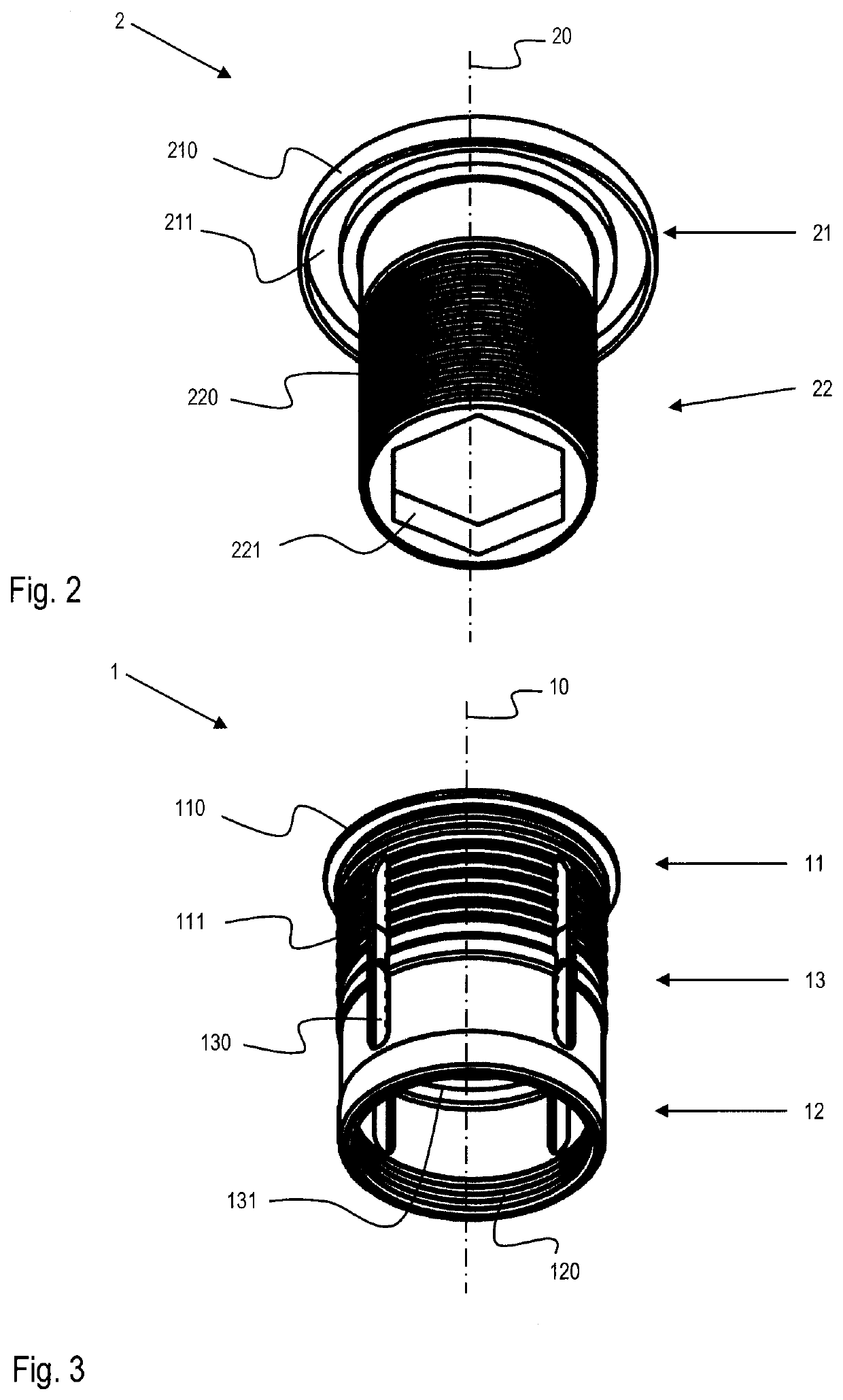
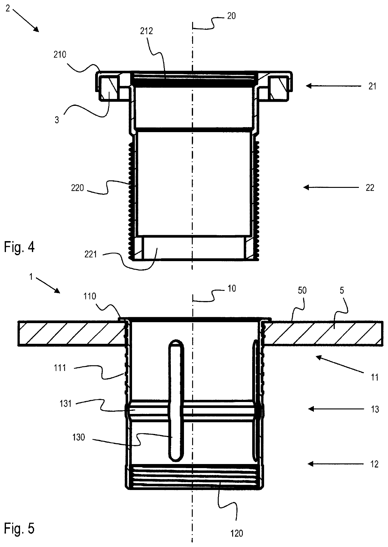
[0006]An installation device according to the invention for installing flush-mounted fixtures on or in a wall comprises a wall plug and a retainer that can be screwed therein.

[0007]The wall plug has a sleeve-shaped body extending along a first longitudinal axis that has a first free end, a second, opposite free end, and a securing section therebetween. There is a first free end surface limit stop at the first free end of the wall plug and a first tightening element at the second free end of the wall plug.

[0008]The retainer has a sleeve-shaped body extending along a second longitudinal axis that has a first free end and an op...


PUM


Abstract

An installation device for installing flush-mounted fixtures on/in a wall, where the installation device has a wall plug and a retainer that can be screwed therein. The wall plug and the retainer have a sleeve-shaped body, and a relative rotation between the wall plug and the retainer in a first direction of rotation leads to a reduction in the distance between a first free end and a second free end of the wall plug, and that a relative rotation between the wall plug and the retainer in a second direction of rotation, opposite the first, leads to an increase in the distance between the first free end and the second free end of the wall plug.

Description

TECHNICAL FIELD[0001]The present invention relates to an installation device for installing flush-mounted fixtures.PRIOR ART[0002]With flush-mounted installation, flush-mounted sockets, flush-mounted switches, flush-mounted control units, or flush-mounted telephone outlets, flush-mounted antenna outlets, flush-mounted dimmers, flush-mounted thermostats, and so-called outlet sockets, are used for installing flush-mounted fixtures. There are various designs for outlet sockets, wherein the simplest form is in the shape of a socket, and has a uniform diameter above the depth of the socket. Outlet sockets are normally made of plastic and have screw heads to which fixture inserts can be attached.[0003]Such outlet sockets take up a lot of space and are difficult to install. Furthermore, different sockets are used in different types of walls, e.g. solid walls (e.g. with plaster surfaces or coated with plates) or hollow walls (e.g. plaster walls or lightweight walls). A retaining or securing...

Claims


Application Information

Patent Timeline
IPC IPC(8): H02G3/12H02G3/18
CPCH02G3/123H02G3/18H02G3/20
Inventor OBRIST, ROLANDKNUPFER, DANIEL
Owner OBLAMATIK AG
Why Eureka
Try Eureka