Wheel disk assembly having sealing plates

Active Publication Date: 2017-08-24
SIEMENS ENERGY GLOBAL GMBH & CO KG
View PDF2 Cites 1 Cited by
  • Summary
  • Abstract
  • Description
  • Claims
  • Application Information

AI Technical Summary

Benefits of technology

[0007]According to the invention, the at least one bolt has, at its end region oriented away from the wheel disk, at least one radially outwardly protruding projection as a bearing surface for an associated sealing plate. This ensures secure and proper positioning of the sealing plates while maintaining a defined separation between the wheel disk and the sealing plates.
[0008]According to a first embodiment, the bolts are configured such that, in their final installation position, braced against the base of the bore, they press resiliently against the faces of the sealing plates oriented toward the wheel disk. This ensures a play-free and thus low-wear fit of the bolt in the cutout of the sealing plate.
[0009]Advantageously, the bore can be untapped, such that the strength of the wheel dis

Problems solved by technology

However, one problem of a securing device so formed is that the notch effect associated with the tapped hole provided in the wheel disk negatively affects the strength of the wheel disk, and can give rise to corresponding problems.
Furthermore, it is often the case that sc

Method used


Image

  • Wheel disk assembly having sealing plates
  • Wheel disk assembly having sealing plates
  • Wheel disk assembly having sealing plates

Examples


Example

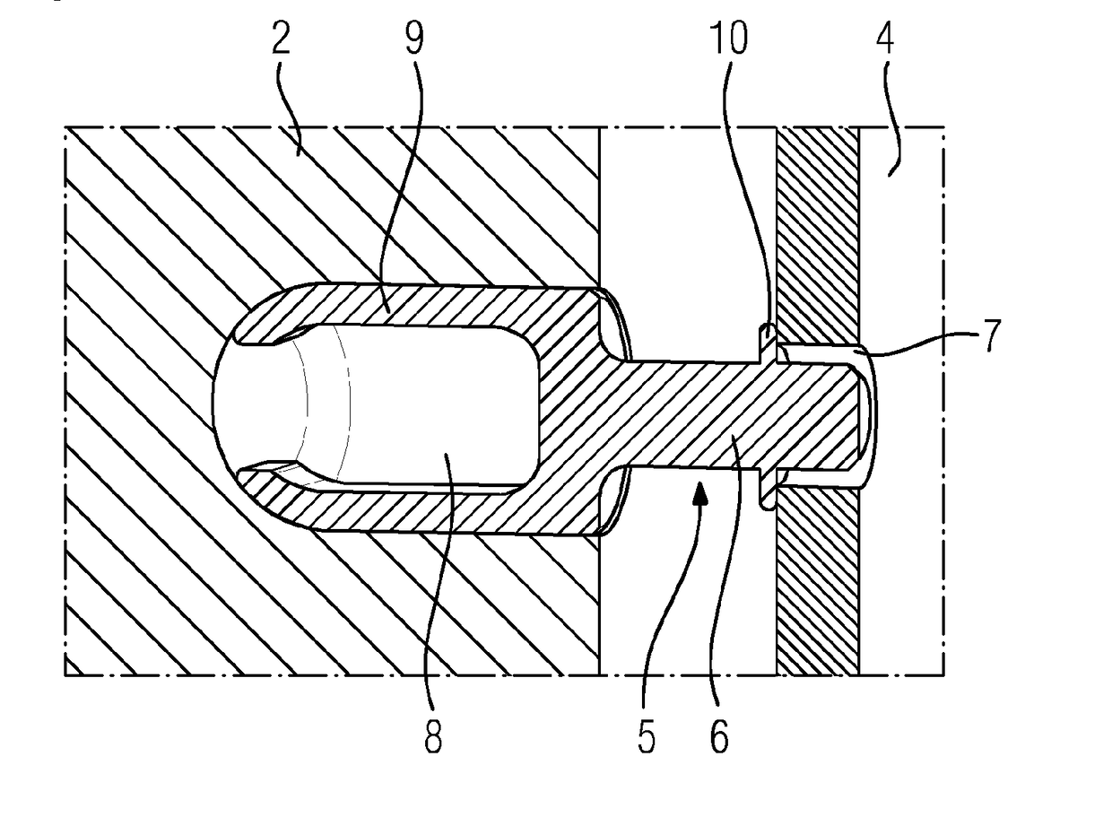
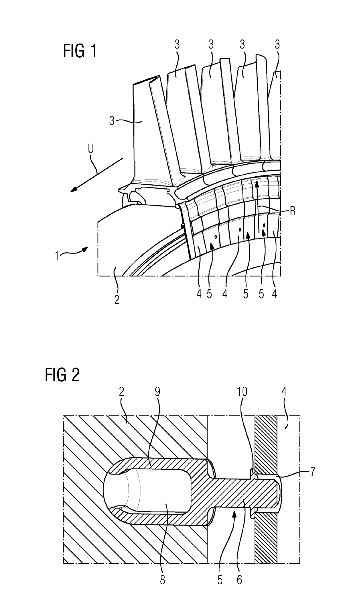
[0022]FIGS. 1 to 5 show a wheel disk assembly 1 according to one embodiment of the present invention, or components thereof. The wheel disk assembly 1 comprises a wheel disk 2, multiple blade devices 3 which are attached along an outer circumference of the wheel disk 2, and multiple sealing plates 4 which extend between the wheel disk 2 and the blade devices 3, and are received such that they can be displaced in the circumferential direction U. More precisely, the sealing plates 4 are inserted into annular grooves which are arranged spaced apart from one another in the radial direction R, the annular grooves being formed on the one hand in the wheel disk 2 and on the other hand in the blade devices 3.

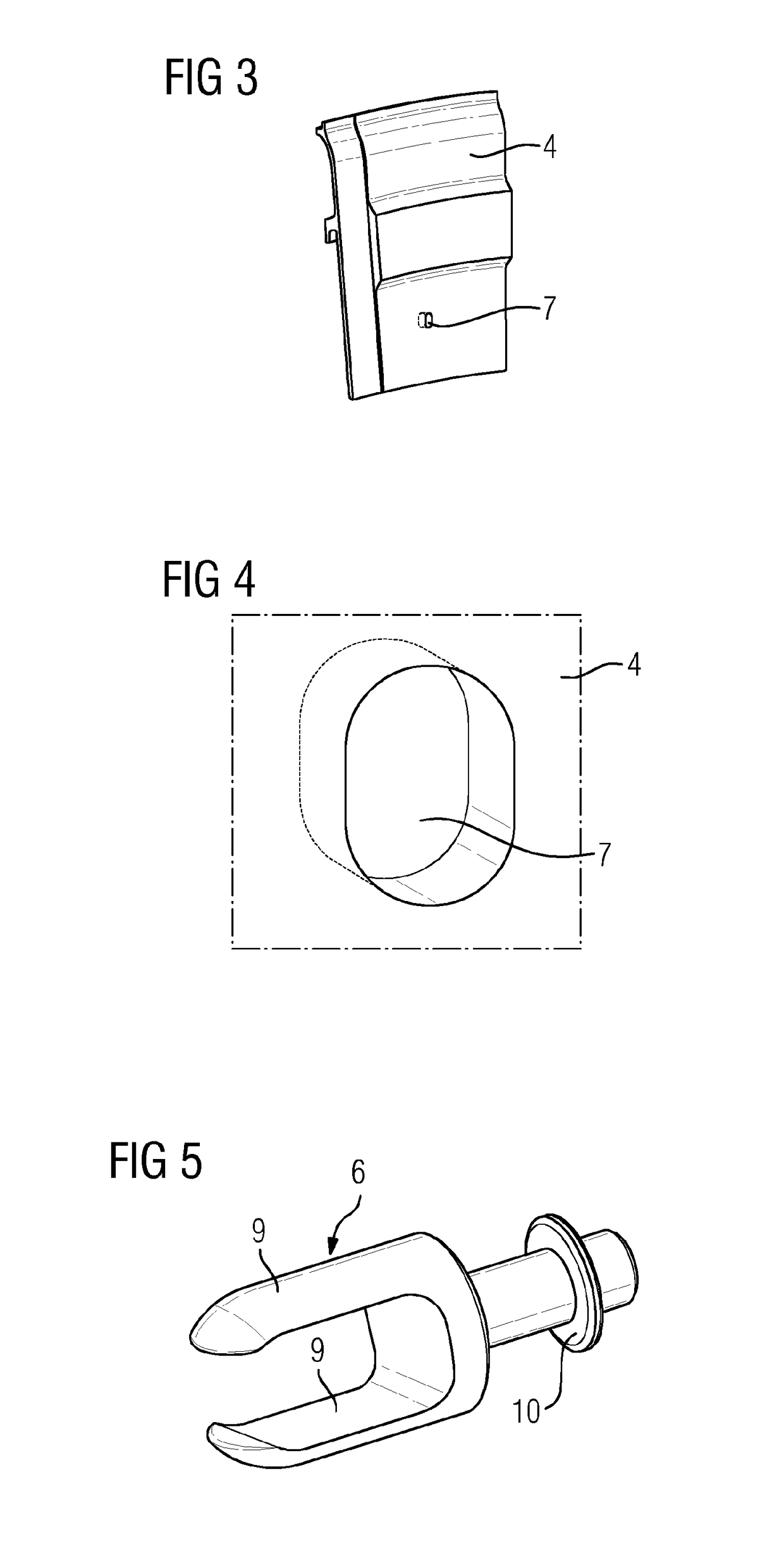
[0023]In order to secure the sealing plates 4 against displacement in the circumferential direction U, the wheel disk assembly 1 comprises multiple securing devices 5, in the present case one securing device 5 for each sealing plate 4. Each securing device 5 has a bolt 6 which is attach...


PUM


Abstract

A wheel disk assembly having a wheel disk, a plurality of blade devices fastened along an outer circumference of the wheel disk, a plurality of sealing plates accommodated between the wheel disk and the blade devices such that the sealing plates are moveable in the circumferential direction, and securing devices designed such that the securing devices secure the sealing plates against movement in the circumferential direction. Pins are provided as securing devices, which pins are detachably retained in bores arranged on the wheel disk and reach into recesses that are formed on surfaces of the sealing plates facing the wheel disk, wherein at least one of the pins, preferably all of the pins, are designed such that, in order to disengage a pin from the associated recess, the pin in question can be plunged further into the bore in a resilient manner.

Description

CROSS REFERENCE TO RELATED APPLICATIONS[0001]This application is the US National Stage of International Application No. PCT / EP2015 / 073548 filed Oct. 12, 2015, and claims the benefit thereof. The International Application claims the benefit of European Application No. EP14191066 filed Oct. 30, 2014. All of the applications are incorporated by reference herein in their entirety.FIELD OF INVENTION[0002]The present invention relates to a wheel disk assembly, having a wheel disk, a plurality of blade devices, which are fastened along an outer circumference of the wheel disk, a plurality of sealing plates, which are received between the wheel disk and the blade devices such that they can be displaced in the circumferential direction, and securing devices designed so as to secure the sealing plates against displacement in the circumferential direction, wherein bolts are provided as securing devices, which bolts are releasably held in bores arranged in the wheel disk and engage in cutouts f...

Claims


Application Information

Patent Timeline
IPC IPC(8): F01D5/30F01D11/00
CPCF01D5/3015F05D2260/30F05D2220/32F01D11/005F05D2230/64F05D2260/37F01D5/323F01D5/326F01D11/006
Inventor KAMPKA, KEVINKOWALZIK, CHRISTIANSCHRODER, PETERVEITSMAN, VYACHESLAV
Owner SIEMENS ENERGY GLOBAL GMBH & CO KG
Why Eureka
Try Eureka