Method of making a vehicle antenna

Active Publication Date: 2010-06-10
HIRSCHMANN CAR COMMUNICATION
View PDF4 Cites 0 Cited by
  • Summary
  • Abstract
  • Description
  • Claims
  • Application Information

AI Technical Summary

Benefits of technology

[0004]The object of the invention is therefore to provide a method of making a vehicle antenna, and a vehicle antenna produced using this method that is further improved with regard to the production, storage, and also with regard to the installation thereof.
[0005]According to the invention the method of making the vehicle antenna is characterized in that a plug-type connector is attached to a base of the antenna elements, or an electronic device is applied to the support film and is electrically contacted. This provides the advantage that the plug-type connector or the electronic device, preferably an antenna amplifier, is fixed directly on the support film (2) and electrically contacted directly at the base of the antenna elements (3) to which high-frequency signals are to be transmitted via the plug-type connector or are to be processed further dire

Problems solved by technology

However, this has the disadvantage that an extra support film and the connection line located thereon mu

Method used


Image

  • Method of making a vehicle antenna
  • Method of making a vehicle antenna
  • Method of making a vehicle antenna

Examples


Example

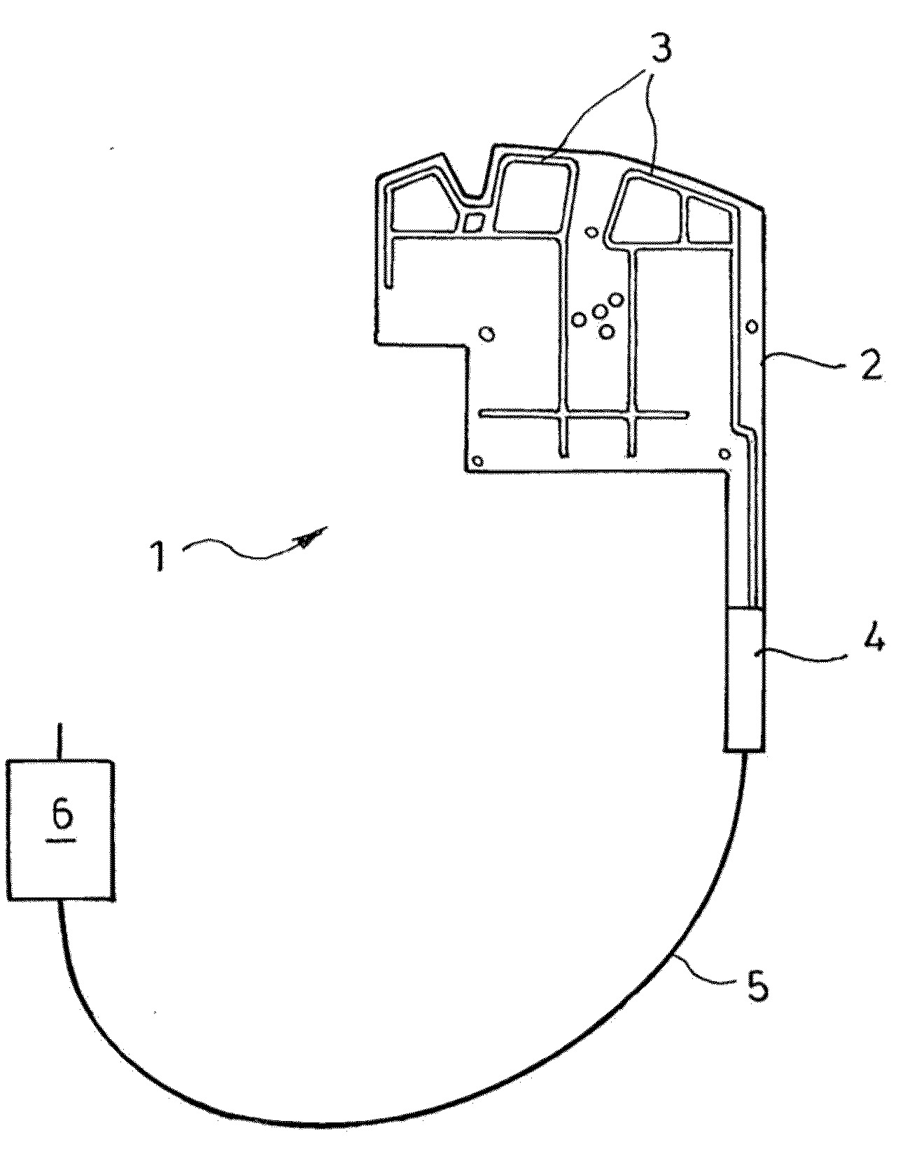
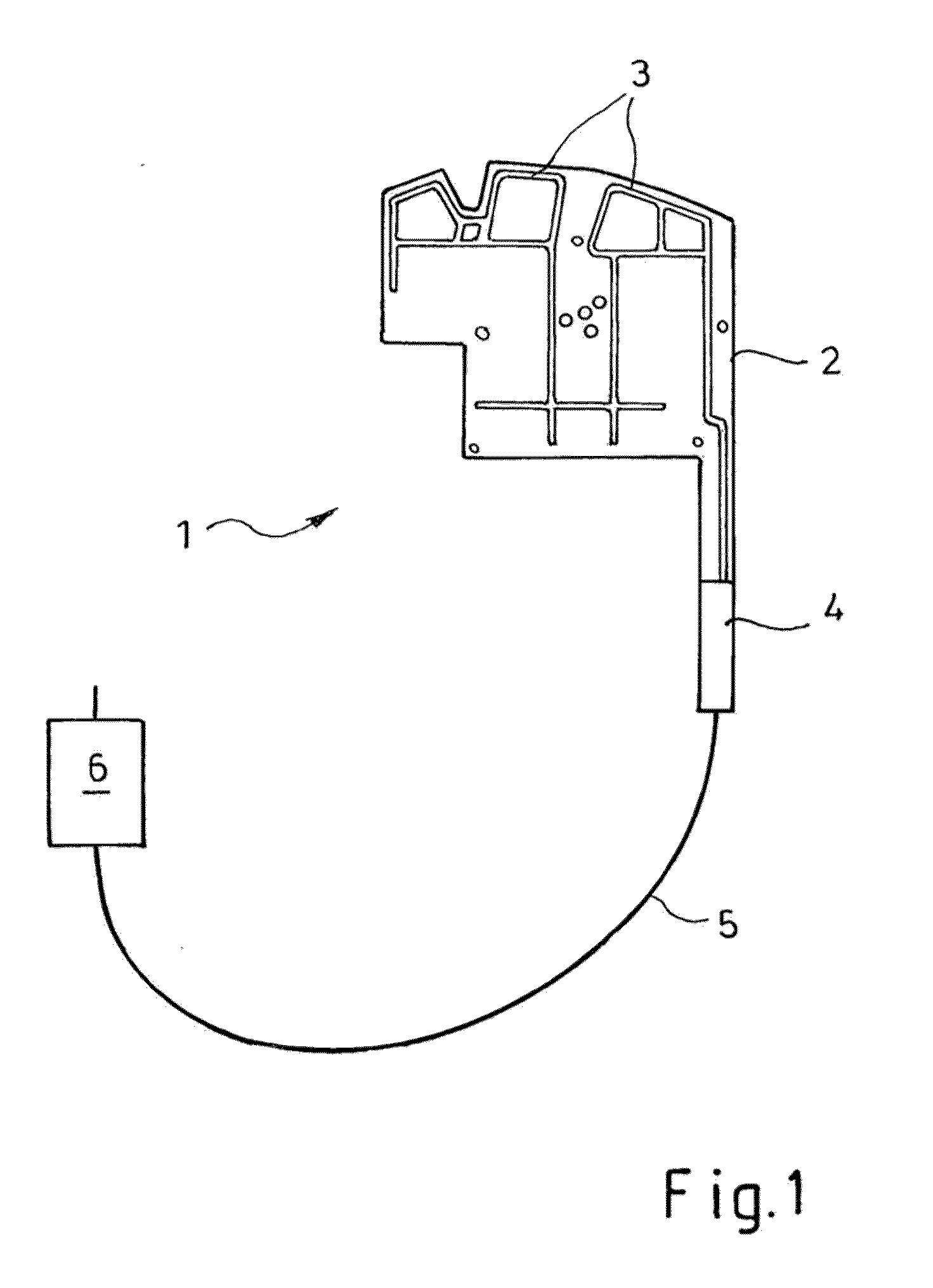
[0012]FIG. 1 shows in detail a vehicle antenna 1, where one or more antenna elements 3 are carried by a support film 2 of a dielectric material, particularly a flexible plastic film. The fixing of the antenna elements 3 is advantageously done by printing, such as screen printing an electrically conductive paste, preferably a silver polymer paste, onto the flat support film 2. Other methods of application and other materials are also conceivable for the antenna elements 3. A tab projects from the support film 2 and carries a plug-type connector 4 at an end forming a base of the antenna elements 3. This way, an unillustrated connector matable with the plug-type connector 4 can be mechanically and electrically connected to the base of the antenna elements 3. This can be cone, for example, by crimping, soldering, or other processes. The vehicle antenna 1 is connected by the plug-type connector 4 to an electronic device, such as an antenna amplifier, an impedance converter, a receiver, o...


PUM

PropertyMeasurementUnit
Electrical conductivityaaaaaaaaaa
Shapeaaaaaaaaaa

Abstract

The invention relates to a method for producing a vehicle antenna device (1) and to a vehicle antenna device (1) which is produced using this method and has a carrier film (2) which is composed of an electrically non-conductive material, wherein antenna structures (3) which are composed of an electrically conductive material are applied to the carrier film (2), wherein provision is made, according to the invention, for a plug connector (4) or an electronic device (6) to be fixed and electrically contact-connected directly to the carrier film (2) at a base point of the antenna structure (3).

Description

CROSS REFERENCE TO RELATED APPLICATIONS[0001]This application is the US national phase of PCT application PCT / EP2008 / 008776, filed 16 Oct. 2008, published 23 Apr. 2009 as WO2009 / 049891, and claiming the priority of German patent application 102007049433.7 itself filed 16 Oct. 2007 and German patent application 102007062142.8 itself filed 21 Dec. 2007, whose entire disclosures are herewith incorporated by reference.FIELD OF THE INVENTION[0002]The invention relates to a method of making a vehicle antenna and to a vehicle antenna produced using this method.BACKGROUND OF THE INVENTION[0003]Methods are known of making vehicle antennas that have a is support film of a dielectric material, antenna elements and leads of an electrically conductive material on the support film. Furthermore, one or more connection lines are carried by the support film for connection of the antenna elements, or multiple antenna elements to an electronic device, particularly an antenna amplifier. However, this h...

Claims


Application Information

Patent Timeline
IPC IPC(8): H01Q1/32H05K13/00
CPCB60R1/12B60R2001/1261H01Q1/3266Y10T29/49016H01R2201/02H01R2201/26H01Q1/38
Inventor DAUM, UWEKREISSIG, UWEPFLETSCHINGER, MARKUSSCHWARZ, BERND
Owner HIRSCHMANN CAR COMMUNICATION
Why Eureka
Try Eureka