Cutting apparatus

Active Publication Date: 2019-09-19
DISCO CORP
View PDF0 Cites 2 Cited by
  • Summary
  • Abstract
  • Description
  • Claims
  • Application Information

AI Technical Summary

Benefits of technology

The present invention provides a cutting apparatus with a blade changing apparatus that can quickly and reliably mount or remove cutting blades from the blade mount on the spindle. The blade changing apparatus includes a first holding portion that can hold the circular base of the cutting blade and adjust its angle to match the profile of the blade mount, and a second holding portion that can adjust the angle of the fixing nut so it matches the profile of the blade mount when the fixing nut is mounted over the blade mount. This ensures a secure and reliable mounting of the cutting blade on the spindle, and reduces the possibility of tilting or misalignment during the process.

Problems solved by technology

This positional adjustment involves a heavy workload.

Method used


Image

  • Cutting apparatus
  • Cutting apparatus
  • Cutting apparatus

Examples


Embodiment Construction

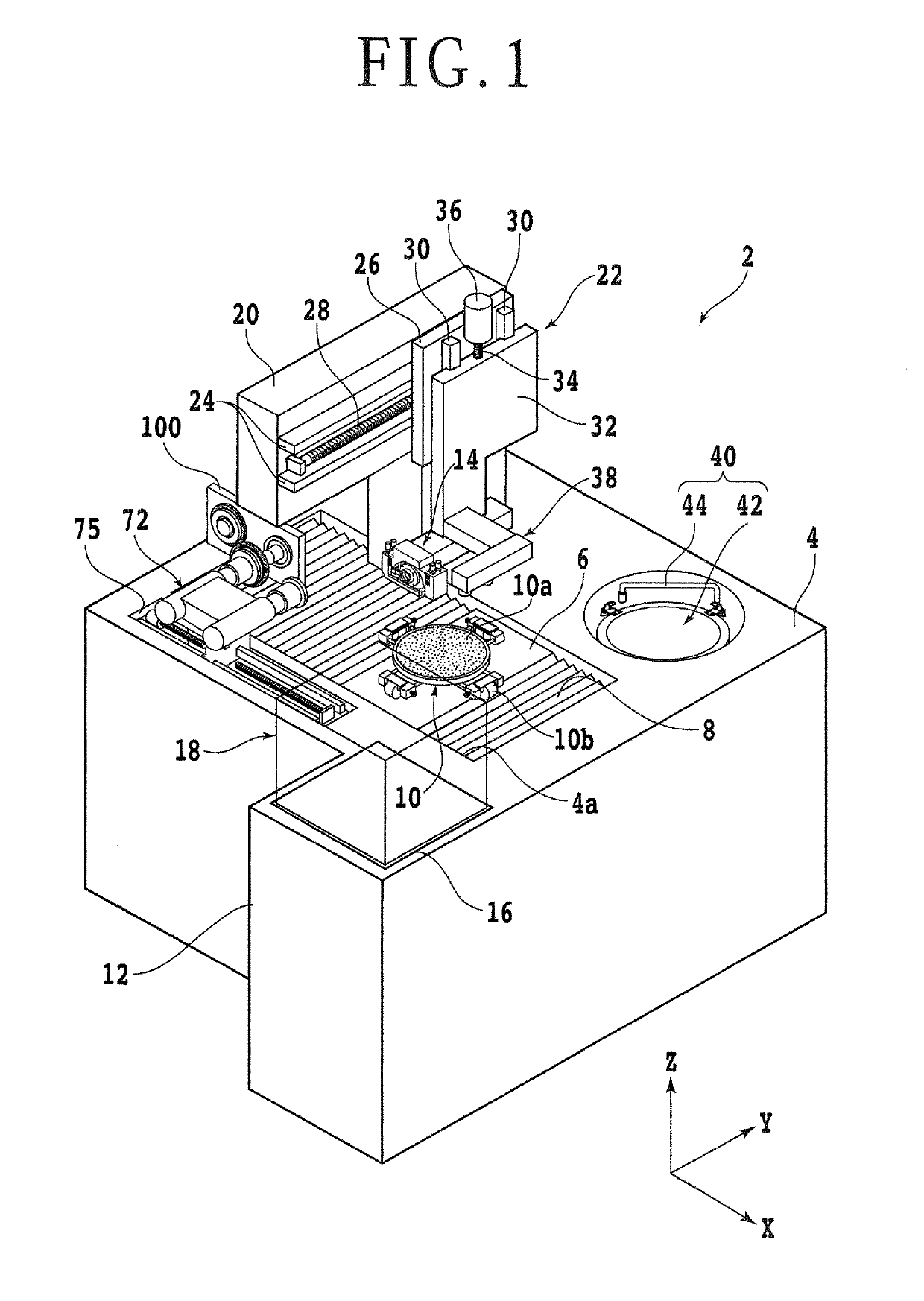
[0029]Embodiments of the present invention will be described in detail below with reference to the accompanying drawings. FIG. 1 is a perspective view depicting a cutting apparatus 2 including a blade changing apparatus 72 according to an embodiment of the present invention. As depicted in FIG. 1, the cutting apparatus 2 includes an apparatus base 4. The apparatus base 4 supports various elements constituting the cutting apparatus 2. The apparatus base 4 has an upper surface having an opening 4a formed therein. The opening 4a has a rectangular shape elongated in an X-axis direction (feeding direction).

[0030]An X-axis moving table 6, an X-axis moving mechanism (not depicted), and a dust-proof and drip-proof cover 8 are disposed inside the opening 4a. The X-axis moving mechanism moves the X-axis moving table 6 in the X-axis direction. The dust-proof and drip-proof cover 8 covers the X-axis moving mechanism. The X-axis moving mechanism includes a pair of X-axis guide rails (not depicte...


PUM

PropertyMeasurementUnit
Forceaaaaaaaaaa

Abstract

A cutting apparatus includes a blade changing apparatus. The blade changing apparatus includes a blade mounting and removal portion, which in turn includes: a holding portion that removably holds a circular base of a cutting blade; a moving support portion that supports the holding portion and moves the holding portion to a removal and mounting position at which an insertion hole in the blade faces a boss of a blade mount; and a coupling mechanism that couples the holding portion with the moving support portion such that the holding portion is freely tiltable with respect to the moving support portion. The coupling mechanism includes a plurality of elastic member pairs, each pair, while tensioning the holding portion in opposite directions, fixing the holding portion to the moving support portion. Forces acting from the elastic member pairs balance each other to thereby support the holding portion tiltably and aerially.

Description

BACKGROUND OF THE INVENTIONField of the Invention[0001]The present invention relates to a cutting apparatus including a blade changing apparatus.Description of the Related Art[0002]A known cutting apparatus incorporates a cutting blade that cuts a plate-shaped workpiece, such as a semiconductor wafer and an optical device wafer having a front surface on which a plurality of devices are formed, and a resin package substrate, into divided chips. The cutting blade needs replacement at regular intervals because a cutting edge of the cutting blade wears out through use.[0003]A cutting blade replacement procedure typically includes insertion of the cutting blade into a boss of a blade mount disposed at a distal end of a spindle of the cutting apparatus and fixing of the cutting blade with a fixing nut. Fitting the cutting blade into the boss of the blade mount requires a certain level of skill. A cutting blade, if inserted obliquely, can damage the blade mount or can be fixed in an obliqu...

Claims


Application Information

Patent Timeline
IPC IPC(8): B23Q3/155B26D7/26B26D5/22H01L21/304
CPCH01L21/304B23Q3/155B23D35/008B26D7/2614B26D5/22B28D5/022B28D5/0058B28D5/0076B26D7/2621B26D1/16B26D7/08B23Q3/15713B28D5/024B24B41/068B23Q3/157B23D45/022
Inventor TERADA, KAZUKI
Owner DISCO CORP
Why Eureka
Try Eureka