Direction of arrival estimation

a technology of direction and arrival, applied in the direction of direction finders, diversity direction finding, instruments, etc., can solve the problems of increasing the throughput of the overall network, uninterrupted communication between users, and doa problems

Active Publication Date: 2019-09-26
MACQUARIE UNIV
View PDF0 Cites 12 Cited by
  • Summary
  • Abstract
  • Description
  • Claims
  • Application Information

AI Technical Summary

Benefits of technology

The technical effect of this patent is that it describes how a processor can receive inputs from multiple sensors placed in different locations and use those inputs to determine which way certain signals are coming from. This process involves analyzing the phases of the signals and comparing them with pre-known information about the placement of the sensors. By iteratively adjusting the position of the sensors and recalculating the analysis, the system can estimate the direction of arrival for various signals. Ultimately, this technology allows for better tracking and location identification of objects or people through the use of multiple sensors.

Problems solved by technology

The technical problem addressed in this patent text is the need for precise estimation of the direction of arrival (DOA) of radio transmitters in various applications, such as cellular networks, radio navigation, object location, and radar. The accuracy of the DOA determination is crucial for efficient network operation, resource allocation, and identifying unauthorized users. The problem also arises in relation to determining the location of a sonar system. The precision of the transmitter location depends on the accuracy of the angle of arrival, which requires minimizing errors and can be achieved using triangulation. The solution should be applicable on low computationally capable platforms and with low power consumption hardware or processors.

Method used


Image

  • Direction of arrival estimation
  • Direction of arrival estimation
  • Direction of arrival estimation

Examples


example process

[0215 Flow

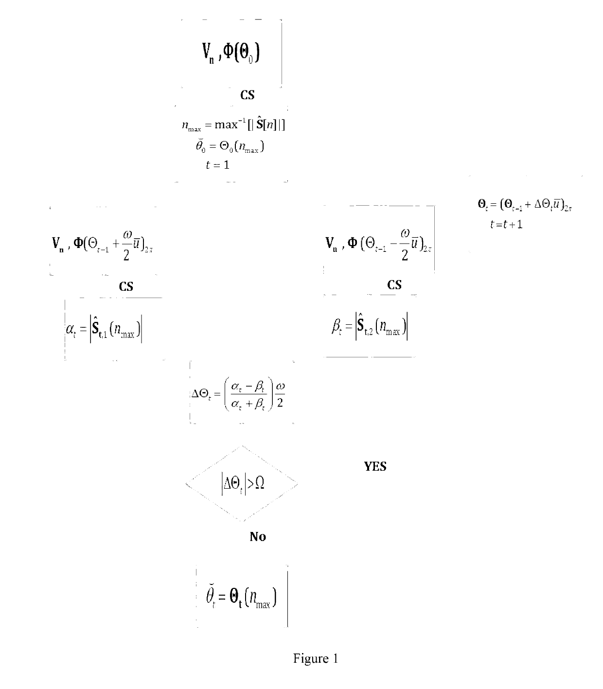
[0216]FIG. 1 shows an example process flow for determining an estimated direction of arrival of a signal at an array of M antenna elements. An initial grid of N candidate directions of arrival is defined, with N greater than M to result in a sparse problem. The grid is rotated in both directions and an angular discriminant determined based on the rotated grid. The angular discriminant controls the extent of rotation of any subsequent iterations. An estimated direction of arrival is output when a threshold condition is met.

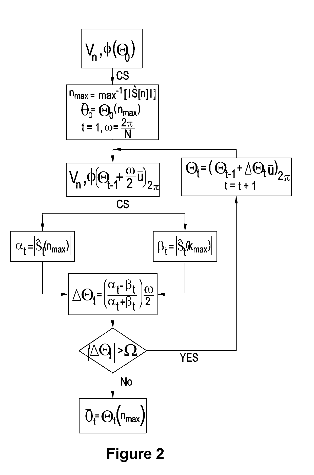
[0217]FIG. 2 shows another example process flow for determining an estimated direction of arrival of a signal at an array of M antenna elements. An initial grid of N candidate directions of arrival is defined, with N greater than M to result in a sparse problem. After an initial compressive sensing determination, the grid is rotated and the compressive sensing determination repeated. An angular discriminant is determined based on the solution vectors. The...


PUM


Abstract

Iterative methods for direction of arrival estimation of a signal at a receiver with a plurality of spatially separated sensor elements are described. A quantized estimate of the angle of arrival is obtained from a compressive sensing solution of a set of equations. The estimate is refined in a subsequent iteration by a computed error based a quantized estimate of the direction of arrival in relation to quantization points offset from the quantization points for the first quantized estimate of the angle of arrival. The iterations converge on an estimated direction of arrival.

Description


Claims


Application Information

Patent Timeline
Owner MACQUARIE UNIV
Why Eureka
Try Eureka