
Hair removal device

a technology for hair removal and hair, which is applied in the direction of hair cleaning, hair singing, metal working apparatus, etc., can solve the problems of increasing the inertia of affecting the effect of the user, and applying a rather high contact pressure, so as to improve the working head structure, improve self-adaption, and improve the effect of control

Active Publication Date: 2019-10-03
BRAUN GMBH
View PDF2 Cites 5 Cited by
  • Summary
  • Abstract
  • Description
  • Claims
  • Application Information

AI Technical Summary

Benefits of technology

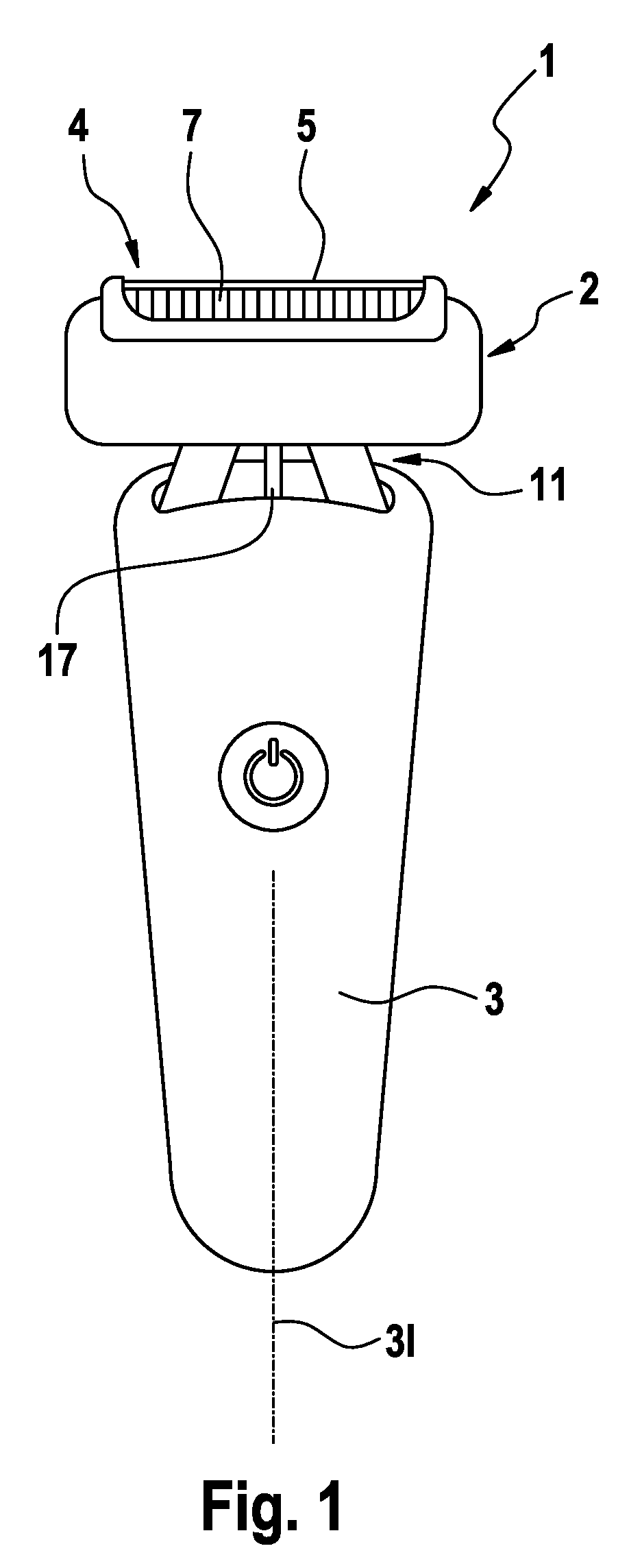
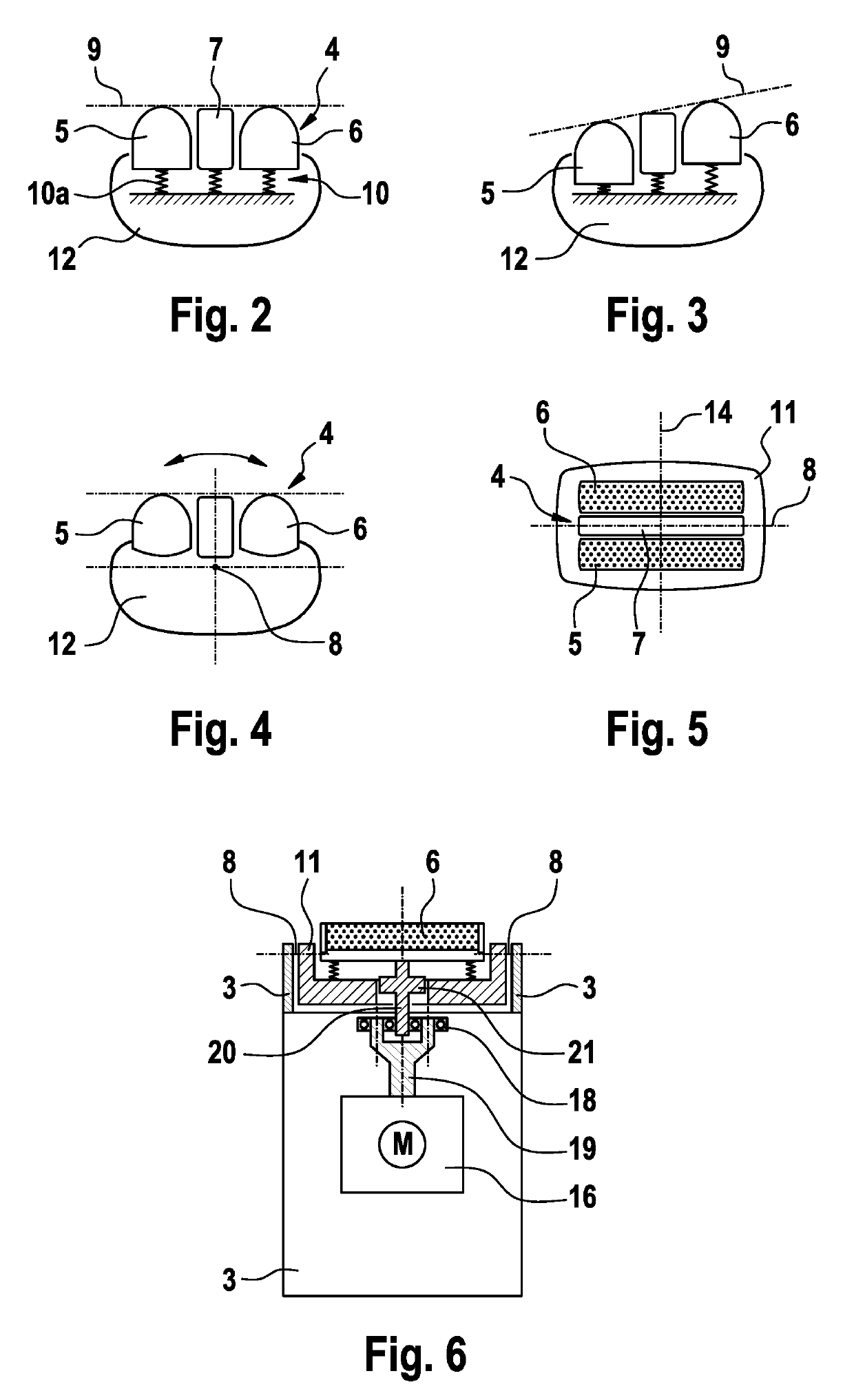
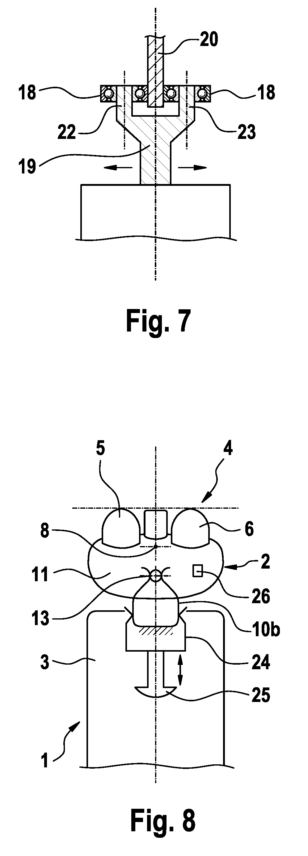
The present invention provides an improved hair removal device with a pivoting working head that can adjust to varying skin contents and surface orientations. The device allows for easy self-adaption to complex skin contours while maintaining a good feel of control during hair removal. The pivot range adjustment device can increase the pivoting resistance to provide better control when reducing the pivot range. These improvements enhance the performance and comfort of the hair removal device.

Problems solved by technology

With such self-adjusting working heads and hair removal tools it is nevertheless a problem to achieve a sufficient self-adaption to the skin contour and skin surface orientation on the one hand and, at the same time, give the user the feeling of control when increasing the skin contact pressure to achieve a thorough hair removal at a particular area.
One reason for insufficient self-adaption is the fact that some users wish to have a mild treatment and press the working head only gently onto the skin.
On the other hand, there are some users applying a rather high contact pressure to achieve thorough hair removal, e.g., at the upper lip region below the nose, what is detrimentally affected by too much self-adaption by the working head's skin contact contour.
Such counterbalancing weight, however, significantly increases the inertia of the working head structure and thus reduces the agility of the hand-held device.

Method used


Image

  • Hair removal device
  • Hair removal device
  • Hair removal device

Examples


Embodiment Construction

[0030]To achieve better adaption to the skin contour and compensation of “wrong” orientation of the handle, the hair removal device has an improved working head structure allowing for pivoting movements of the working head's skin contact contour over a wide angular range even when the working head is carefully slid along the skin to achieve a gentle treatment thereof. More particularly, the skin contact contour of the working head is allowed to pivot over a rather large range under small contact forces. According to an aspect the support structure movably supporting the hair removal tool relative to the handle and the biasing device biasing the hair removal tool into a changed position which may be but don't need to be a neutral position in the absence of skin contact pressure, is configured to allow for pivoting of the skin contact contour relative to the handle about an angle of + / −15° or more under a contact force of 0.75 N or less and / or about an angle of + / −25° or more under a ...


PUM


Abstract

The present invention relates to a hair removal device, in particular electric shaver, comprising a working head attached to a handle for moving the working head along a skin surface, said working head including at least one hair removal tool defining a skin contact contour of the working head, wherein said at least one hair removal tool is movable relative to said handle under a skin contact pressure by means of a support structure to allow for pivoting of the working head's skin contact contour relative to the handle: According to an aspect the support structure movably supporting the hair removal tool relative to the handle is configured to allow for pivoting of the skin contact contour relative to the handle about an angle of about + / −15° or more under a contact force of about 0.75 N or less and / or about an angle of about + / −20° or more under a contact force of about 1.5 N or less.

Description

FIELD OF THE INVENTION[0001]The present invention relates to a hair removal device, in particular electric shaver, comprising a working head attached to a handle for moving the working head along a skin surface, said working head including at least one hair removal tool defining a skin contact contour of the working head, wherein said at least one hair removal tool is movable relative to said handle under a skin contact pressure by means of a support structure to allow for pivoting of the working head's skin contact contour relative to the handle.BACKGROUND OF THE INVENTION[0002]Hair removal devices such as an electric shaver, epilators, or beard trimmers usually include different types of hair removal tools so as to allow for removing long hairs as well as medium hairs and short hairs and stubbles, as commonly found in men's beards and women's legs. Short hair cutters may include a movable cutting blade or undercutter which cooperates with a thin, flexible mesh screen or apertured ...

Claims


Application Information

Patent Timeline
IPC IPC(8): B26B19/04B26B19/06B26B19/38B26B19/10
CPCB26B19/3853B26B19/10B26B19/048A45D2026/0095B26B19/063B26B19/386B26B19/388
Inventor FUERST, STEFANEICHHORN, REINHOLDFUELLGRABE, MARTIN
Owner BRAUN GMBH
Learn More