Detecting failure of layer 2 service using broadcast messages

a technology of broadcast messages and layer 2 service, applied in the direction of digital transmission, data switching networks, electrical devices, etc., can solve the problem of difficult detection of layer 2 service failures, and achieve the effect of reducing the time between a failover and reducing the tim

Active Publication Date: 2019-10-03
NICIRA
View PDF5 Cites 68 Cited by
  • Summary
  • Abstract
  • Description
  • Claims
  • Application Information

AI Technical Summary

Benefits of technology

[0007]Additional embodiments utilize the unidirectional broadcast heartbeat signals to decrease the time between a failover and data messages being forwarded to the new active service node as well as detect a failure of the service node cluster. In embodiments with an L2 bump-in-the-wire service between any two interfaces (e.g., between interfaces of two devices, or between two interfaces of a same device) an architecture using different L2 switches between each interface and the service node cluster is used in conjunction with the unidirectional broadcast heartbeat signals to reduce the time to redirect data messages to the new active service node.
[0008]In some embodiments, the switches connecting the interfaces to the service node cluster associate MAC addresses with particular ports of the switch based on incoming data messages. For example, a data message received at the switch on a first port with a source MAC address “MAC1” (e.g., a 48-bit MAC address of the first interface) will cause the switch to associate the first port with the MAC address MAC1 and future data messages with destination address MAC1 will be sent out of the switch from the first port. By sending the heartbeat data messages to the other interface with shorter time intervals between heartbeats than a timeout of a MAC address association (i.e., the time interval before an association between a MAC address and a port is removed) the ports of the switches attached to the active service node can be associated with the correct MAC addresses for the two interfaces more quickly. As a standby node becomes an active node, the broadcast heartbeat data messages will be received and processed by the newly-active service node and the switches will associate the ports connected to the newly-active service node with the appropriate MAC addresses of the two interfaces.

Problems solved by technology

Failure of the layer 2 service is difficult to detect in some instances.

Method used


Image

  • Detecting failure of layer 2 service using broadcast messages
  • Detecting failure of layer 2 service using broadcast messages
  • Detecting failure of layer 2 service using broadcast messages

Examples


Embodiment Construction

[0023]In the following description, numerous details are set forth for the purpose of explanation. However, one of ordinary skill in the art will realize that the invention may be practiced without the use of these specific details. In other instances, well-known structures and devices are shown in block diagram form in order not to obscure the description of the invention with unnecessary detail.

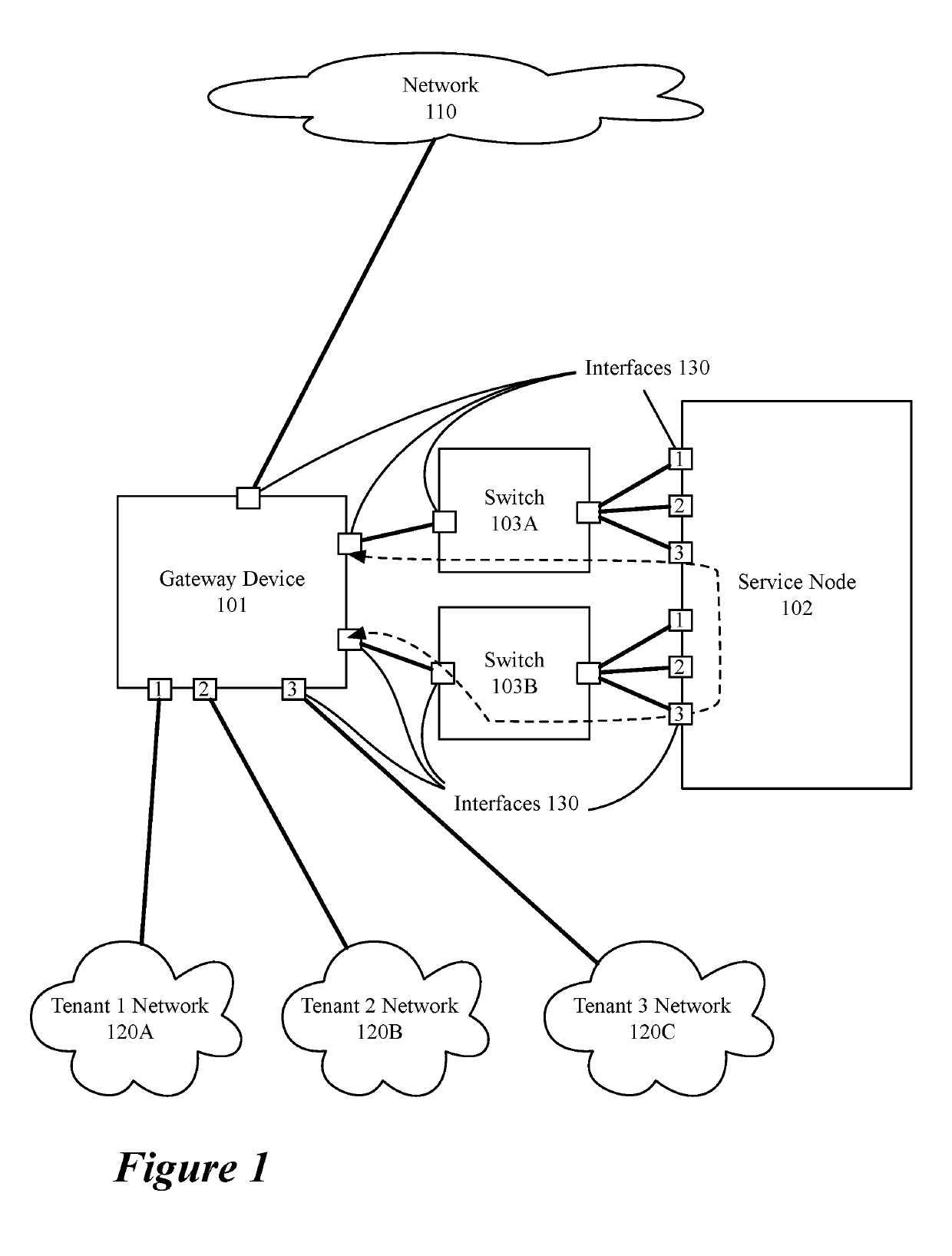
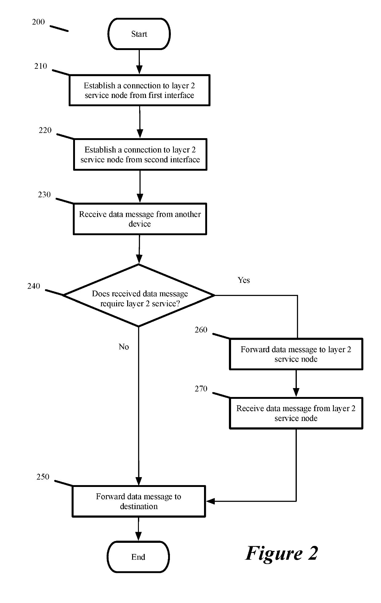
[0024]Some embodiments provide a method for providing a layer 2 (L2) bump-in-the-wire service at a gateway device (e.g., a layer 3 (L3) gateway device) at the edge of a logical network. The method, in some embodiments, establishes a connection from a first interface of the gateway device to a service node that provides the L2 service. The method also establishes a connection from a second interface of the gateway device to the L2 service node. The method then sends data messages received by the gateway device that require the L2 service to the service node using the first interface. In some...


PUM


Abstract

Some embodiments provide a method for detecting a failure of a layer 2 (L2) bump-in-the-wire service at a device. In some embodiments, the device sends heartbeat signals to a second device connected to L2 service nodes in order to detect failure of the L2 service (e.g., a failure of all the service nodes). In some embodiments, the heartbeat signals are unidirectional heartbeat signals (e.g., a unidirectional bidirectional-forwarding-detection (BFD) session) sent from each device to the other. The heartbeat signals, in some embodiments, use a broadcast MAC address in order to reach the current active L2 service node in the case of a failover (i.e., an active service node failing and a standby service node becoming the new active service node). The unidirectional heartbeat signals are also used, in some embodiments, to decrease the time between a failover and data messages being forwarded to the new active service node.

Description

BACKGROUND[0001]In a software defined network, a set of gateway devices (e.g., Edge Nodes) connecting the internal virtualized network and an external network may have a layer 2 bump in the wire service (i.e., a service that does not change the layer 2 addresses of a processed data message) inserted in the processing pipeline. Failure of the layer 2 service is difficult to detect in some instances. When a backup layer 2 service node is provided and a primary layer 2 service node fails, the gateway device must begin sending the data messages to the backup layer 2 service node. A method for learning of the failure and quickly redirecting data messages to the backup layer 2 service node is necessary.BRIEF SUMMARY[0002]Some embodiments provide a method for providing a layer 2 (L2) bump-in-the-wire service at a gateway device (e.g., a layer 3 (L3) gateway device) at the edge of a logical network. The method, in some embodiments, establishes a connection from a first interface of the gate...

Claims


Application Information

Patent Timeline
Patent Type & Authority Applications(United States)
IPC IPC(8): H04L12/26H04L12/24
CPCH04L43/0805H04L43/10H04L41/0668H04L43/0811H04L41/40H04L43/20
Inventor BOUTROS, SAMITAN, STEPHENMISHRA, RAHULMUNDARAGI, KANTESHJAIN, JAYANTNAVEEN, AKHILA
Owner NICIRA
Why Eureka
Try Eureka