Cooling a roll of a roll stand

a technology of cooling device and roll stand, which is applied in the direction of metal rolling arrangement, metal-working apparatus, manufacturing tools, etc., can solve the problems of uncritical spray bar spacing of the roll, and achieve the effect of reducing the friction between the rolling stock and the cooling bar, and reducing the friction between the wiper and the cooling bar

Active Publication Date: 2019-10-10
PRIMETALS TECH AUSTRIA GMBH
View PDF0 Cites 1 Cited by
  • Summary
  • Abstract
  • Description
  • Claims
  • Application Information

AI Technical Summary

Benefits of technology

[0011]A full jet nozzle is taken to mean a nozzle through which a substantially linear coolant jet with a nearly constant jet diameter can be discharged. By virtue of the concentrated discharge of the coolant, full jet nozzles produce a higher impact pressure on the roll than conventionally used fan jet nozzles at the same coolant pressure in the cooling bar. The higher impact pressure has a positive effect on the cooling action directly at the roll surface because there is always a certain coolant film with a typical thickness of several millimeters to centimeters there, owing to the large coolant quantity applied overall. This film should be penetrated as completely as possible by the impinging coolant jets in order to achieve good heat dissipation. Because of the high impact pressure, of the coolant jets on the roll, which pressure is produced by the full jet nozzles, the coolant pressure in the cooling bar can be significantly reduced as compared with the use of fan jet nozzles. This advantageously makes it possible to significantly reduce the energy consumption and operating costs of the cooling device.
[0025]Another embodiment of the invention provides a wiper for wiping coolant from the roll, wherein the wiper and the cooling bar can be pivoted jointly. By means of a wiper, it is advantageously possible to prevent too much coolant from being guided onto the rolling stock and / or into a rolling nip through which the rolling stock is guided between two rolls and washing away a lubricant for reducing the friction between the rolling stock and the rolls, for example. The joint pivotability of the wiper and of the cooling bar advantageously eliminates the need for an additional device for moving the cooling bar. In this case, the advantage, already mentioned above, of using full jet nozzles once again takes effect, namely that using full jet nozzles makes the distance between the spray bar and the roll uncritical over a wide range and therefore makes it unnecessary to adapt it to the roll diameter. Moreover, the invention is also particularly suitable as a retrofitted solution for existing rolling systems with wipers, wherein, for example, only the conventional high pressure spray bars need be replaced by the cooling bars according to the invention.

Problems solved by technology

Since the coolant is discharged through full jet nozzles, the spacing of the spray bar from the roll is furthermore uncritical within a wide range and therefore does not have to be matched to the roll diameter.

Method used


Image

  • Cooling a roll of a roll stand
  • Cooling a roll of a roll stand
  • Cooling a roll of a roll stand

Examples


Embodiment Construction

[0044]In all the figures, corresponding parts are provided with the same reference signs.

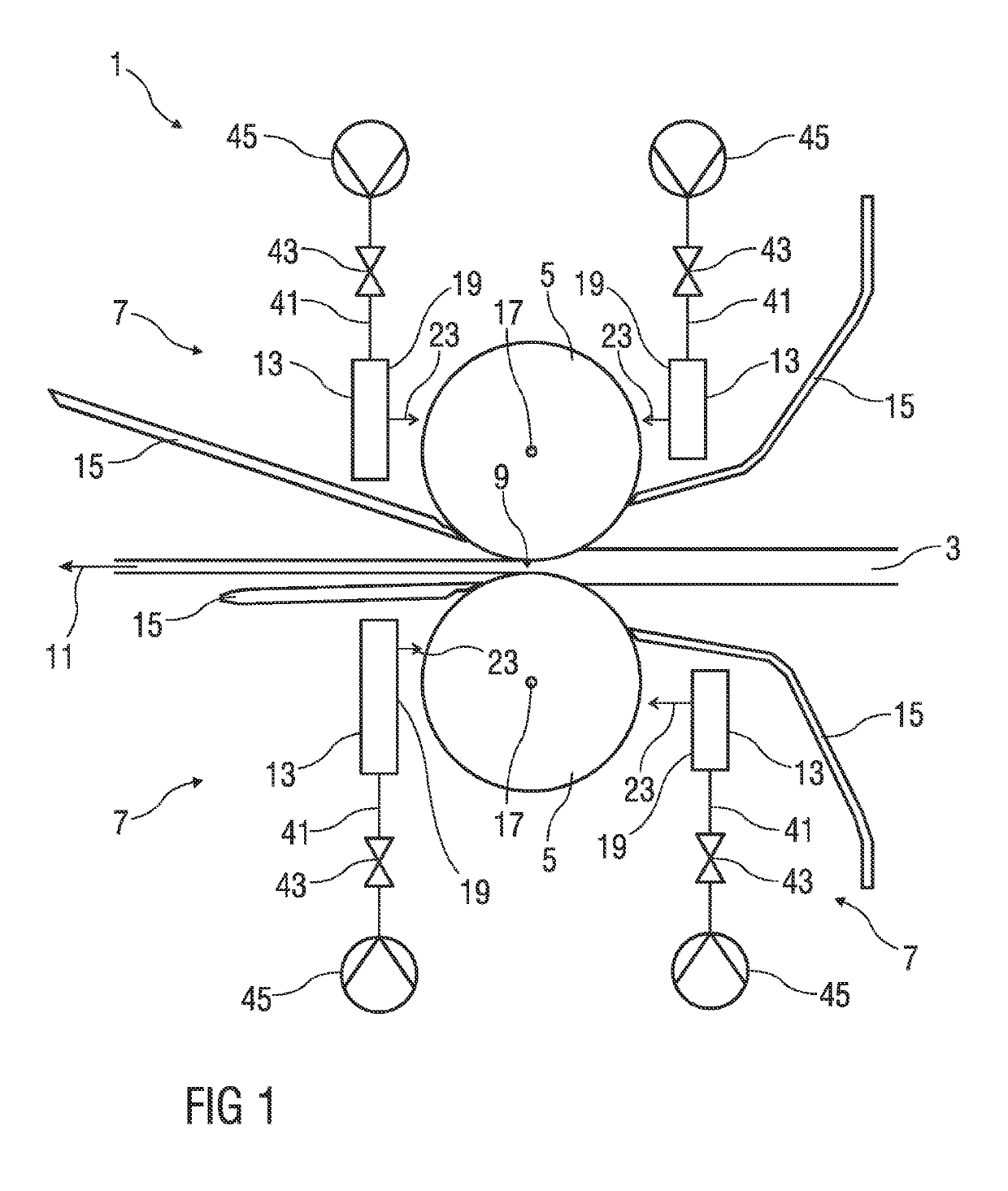
[0045]FIG. 1 shows schematically a roll stand 1 for rolling rolling stock 3. The roll stand 1 comprises two rolls 5 in the form of work rolls and two respective cooling devices 7 for each roll 5. The cooling devices 7 are arranged on different sides of each roll 5. The rolls 5 are spaced apart by a rolling nip 9, through which the rolling stock 3 is passed in a rolling direction 11 in order to form the rolling stock 3.

[0046]Each cooling device 7 comprises a cooling bar 13 and a wiper 15 that wipes coolant off the surface of the roll rolling past the wipers.

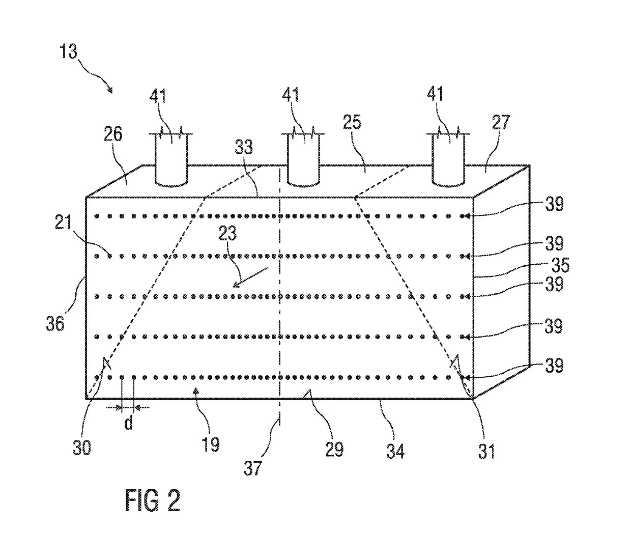
[0047]Each cooling bar 13 is configured to receive a coolant from a source and to discharge the coolant. To discharge the coolant, FIG. 2 shows the cooling bar 13 with a plurality of full jet nozzles 39 arranged on a coolant discharge side 19 of the cooling bar 13. That discharge side faces the respective roll 5 and extends parallel to a roll ...


PUM

PropertyMeasurementUnit
distanceaaaaaaaaaa
distanceaaaaaaaaaa
pressureaaaaaaaaaa

Abstract

A cooling device (7) for cooling a roll (5) of a roll stand (1). The cooling device (7) includes a chilled beam (13) for receiving and discharging a coolant. The chilled beam (13) has multiple full jet nozzles (21) disposed on a discharge side (19) of the chilled beam (13), the side facing the roll (5) and extending parallel to a roll axis (17) of the roll (5). Through each of the full-jet nozzles, a jet of coolant having a nearly constant jet diameter can be sprayed from the chilled beam (13) towards the roll (5) in a discharge direction (23).

Description

CROSS-REFERENCE TO RELATED APPLICATIONS[0001]The present application is a 35 U.S.C. §§ 371 national phase conversion of PCT / EP2017 / 076000, filed Oct. 12, 2017, which claims priority of European Patent Application No. 16194099.4, filed Oct. 17, 2016, the contents of which are incorporated by reference herein. The PCT International Application was published in the German language.TECHNICAL BACKGROUND[0002]The invention relates to a cooling device for cooling a roll of a roll stand.[0003]Roll stands for rolling rolling stock have rolls which are cooled with a cooling liquid, generally cooling water.[0004]US 2010 / 0089112 A1 discloses rigid, concavely shaped shells, by means of which cooling liquid under low pressure can be applied to rolls of a roll stand.[0005]DE 10 2009 053 074 A1 discloses flow cooling of work rolls of a roll stand by means of movable articulated cooling shells. In this case, the cooling liquid is applied predominantly under low pressure with the aid of the cooling s...

Claims


Application Information

Patent Timeline
Patent Type & Authority Applications(United States)
IPC IPC(8): B21B27/10
CPCB21B27/10B21B2027/103
Inventor OPITZ, ERICHPICHLER, LUKASSEILINGER, ALOIS
Owner PRIMETALS TECH AUSTRIA GMBH
Why Eureka
Try Eureka