
Milling tool with coolant flow grooves

a technology of coolant flow and milling tool, which is applied in the direction of adverse effect compensation, milling equipment, metal-working apparatus, etc., can solve the problems of disadvantageous rotary milling tools in a number of respects, and achieve the effect of maximising the service life of the tool

Active Publication Date: 2019-11-14
SANDVIK INTELLECTUAL PROPERTY AB
View PDF0 Cites 0 Cited by
  • Summary
  • Abstract
  • Description
  • Claims
  • Application Information

AI Technical Summary

Benefits of technology

The present invention provides a rotary milling tool that can resist wear and tear when used with high-demand alloys such as heat-resistant superalloys. The tool has cutting teeth and flutes that are designed to effectively dissipate the heat generated during cutting to reduce wear and tear. Cooling grooves are recessed at the land region of each tooth to promote heat exchange and dissipation from the rearward side / region of the teeth. The cooling effect of the fluid is increased as it enters the grooves and is directed and accelerated towards the cutting edges at high speed. This tool design improves the rate of cooling and efficiency of cutting while minimizing wall deviation of the machined workpiece.

Problems solved by technology

Due to the high cutting speeds and considerable thermal stresses at the tool, it is common to deliver liquid coolant to the region of the cutting teeth via the flutes.
However, existing rotary milling tools are disadvantageous in a number of respects.
In particular, heat resistant super alloys (ISOS materials) are typically regarded as ‘sticky’ materials that are difficult to cut and reduce significantly tool lifetimes, with the latter due principally to build-up edge (BUE).
This wear mechanism results from pressure welding of a chip to the tool and is common for low carbon and stainless steels and aluminium based materials at low cutting speeds.

Method used


Image

  • Milling tool with coolant flow grooves
  • Milling tool with coolant flow grooves
  • Milling tool with coolant flow grooves

Examples


Embodiment Construction

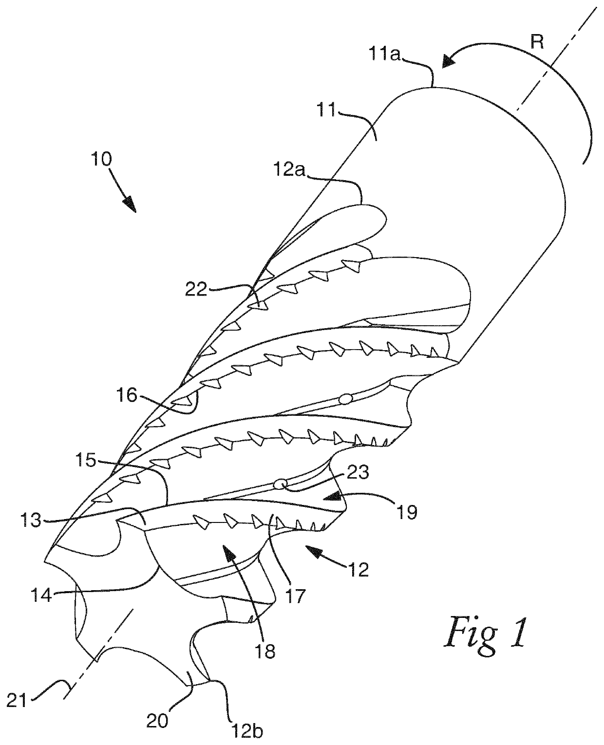
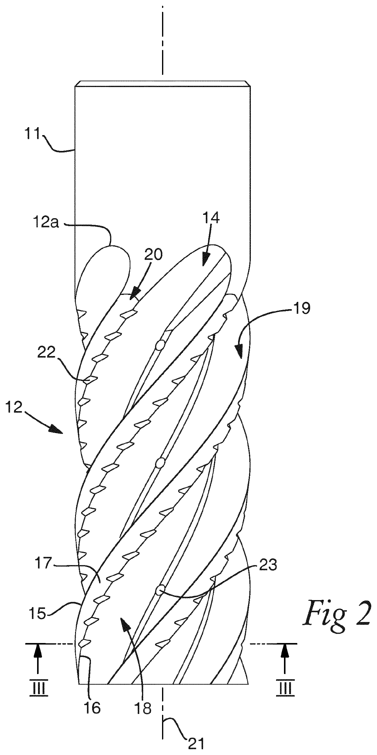
[0028]Referring to FIGS. 1 and 2 an elongate rotary milling tool 10 comprises a head indicated generally by reference 12 and a shaft 11 formed integrally with head 12, with both the head 12 and shaft 11 having a common longitudinal axis 21. Head 12 is provided with 5 helical cutting teeth 20 that extend continuously from a first proximal head end 12a (positioned at the junction between head 12 and shaft 11) and a second distal (or terminal) head end 12b.

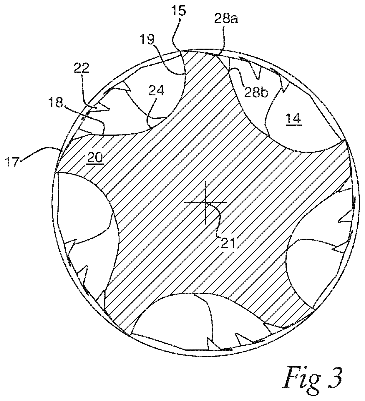
[0029]Teeth 20 are formed as raised ridges extending axially and radially at head 12 relative to axis 21 with neighbouring teeth 20 being separated by corresponding helical flutes 14 in a circumferential direction around axis 21. Accordingly, each tooth 20 is defined by a clearance face 18 and an opposite rake face 19 with a thickness (in the circumferential direction) of each tooth 20 being defined between the opposed clearance and rake faces 18, 19. Clearance face 18 is terminated at a radially outermost region by a helically exte...


PUM


Abstract

A cutting tool having an elongate cutting head provided with a plurality of teeth and flutes in which a plurality of cooling grooves are recessed at a land region of each tooth between a cutting edge and a trailing edge. The grooves at the land do not extend to and are physically separated from the cutting edge to provide a tool optimized for cutting via radially consistent cutting edges and the promotion of heat exchange and dissipation from the rearward side / region of the teeth.

Description

FIELD OF INVENTION[0001]The present invention relates to a rotary milling tool having a plurality of cutting teeth formed at an elongate cutting head.BACKGROUND ART[0002]A wide range of components are machined from many different types of material, with each material having different physical and mechanical characteristics that are influenced by alloying elements, heat treatment, hardness etc. Accordingly, a variety of different cutting and in particular rotary milling tools have been developed to machine workpiece materials. Conventionally, a rotary milling tool comprises a tool body provided with helical or axially straight teeth that are in turn separated by flutes. Due to the high cutting speeds and considerable thermal stresses at the tool, it is common to deliver liquid coolant to the region of the cutting teeth via the flutes. Cooling increases the cutting efficiency of the tool and the service lifetime.[0003]JP 2010-188451 discloses a rotary milling tool comprising helical t...

Claims


Application Information

Patent Timeline
Patent Type & Authority Applications(United States)
IPC IPC(8): B23C5/28
CPCB23C2210/40B23C5/28B23C5/10B23C2250/12B23C2210/32
Inventor PITTALA, GAETANO
Owner SANDVIK INTELLECTUAL PROPERTY AB
Learn More