Image processing apparatus, image processing method, and storage medium

a technology of image processing apparatus and storage medium, applied in the direction of matrix printers, visual presentations, instruments, etc., can solve the problem of insufficient tones in the range, and achieve the effect of suitable contrast and tonality and maintaining luminance values

Active Publication Date: 2019-11-28
CANON KK
View PDF0 Cites 2 Cited by
  • Summary
  • Abstract
  • Description
  • Claims
  • Application Information

AI Technical Summary

Benefits of technology

[0010]The present invention has been made to solve the above problem. Thus, an object of the present invention is to provide a dynamic range conversion method capable of obtaining suitable contrast and tonality on an entire image while also maintaining a luminance value which the creator wishes to maintain.

Problems solved by technology

This makes it impossible to express sufficient tones in the range.

Method used


Image

  • Image processing apparatus, image processing method, and storage medium
  • Image processing apparatus, image processing method, and storage medium
  • Image processing apparatus, image processing method, and storage medium

Examples


first embodiment

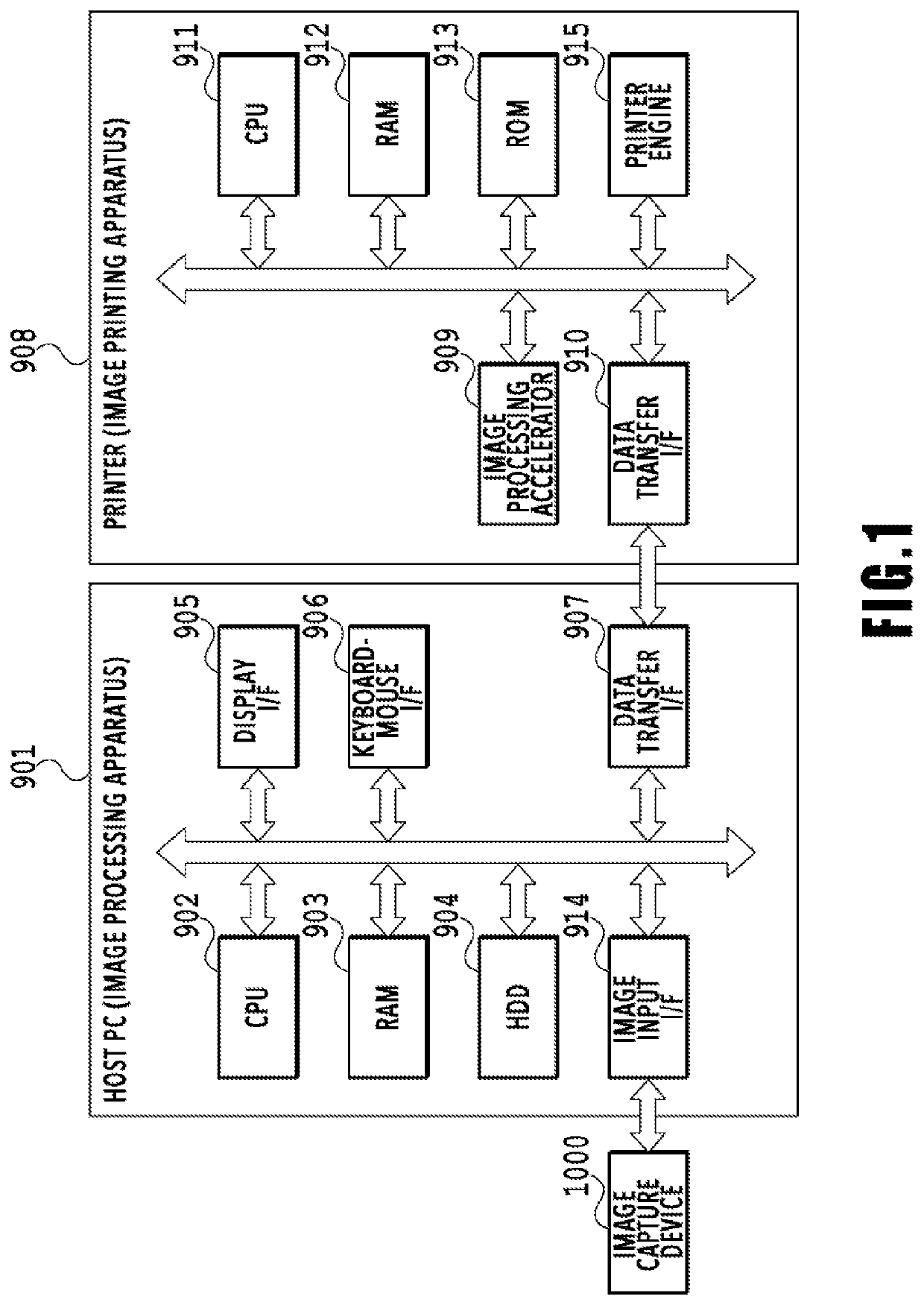
[0026]FIG. 1 is a block diagram for explaining the configuration of a printing system usable in the present invention. A printing system in the present embodiment mainly comprises an image capture device 1000 such as a digital camera, an image processing apparatus 901 such as a personal computer (PC), and an image printing apparatus 908 such as an inkjet printer that ejects ink to print an image. The image capture device 1000 captures an image by using a predetermined sensor and obtains the image as image data. The image data obtained by the image capture device 1000 is inputted into the image processing apparatus 901 through an image input I / F 914. The image data after undergoing predetermined image processing in the image processing apparatus 901 is inputted as print data into the image printing apparatus 908.

[0027]The image printing apparatus 908 prints an image onto a predetermined print medium by following the print data received from the image processing apparatus 901, and out...

second embodiment

[0089]The conversion line for converting the dynamic range described in the first embodiment does not have very high gradients in a luminance value range of 18% and above since the gradient of the conversion line is high in the range of 0 to 18%. Then, in the case of an image containing many pieces of luminance data at or above 18%, the image may give observers the impression that contrast is insufficient.

[0090]To solve such a problem, in the present embodiment, an image region is divided into a plurality of regions, and a suitable conversion line is prepared for each of the divided regions. In each of these conversion lines, the gradient (contrast) in the luminance value range of 0 to 18% is maintained to be similar to that in the first embodiment. On the other hand, as for the range of 18% and above, the gradient is appropriately distributed for each individual divided region.

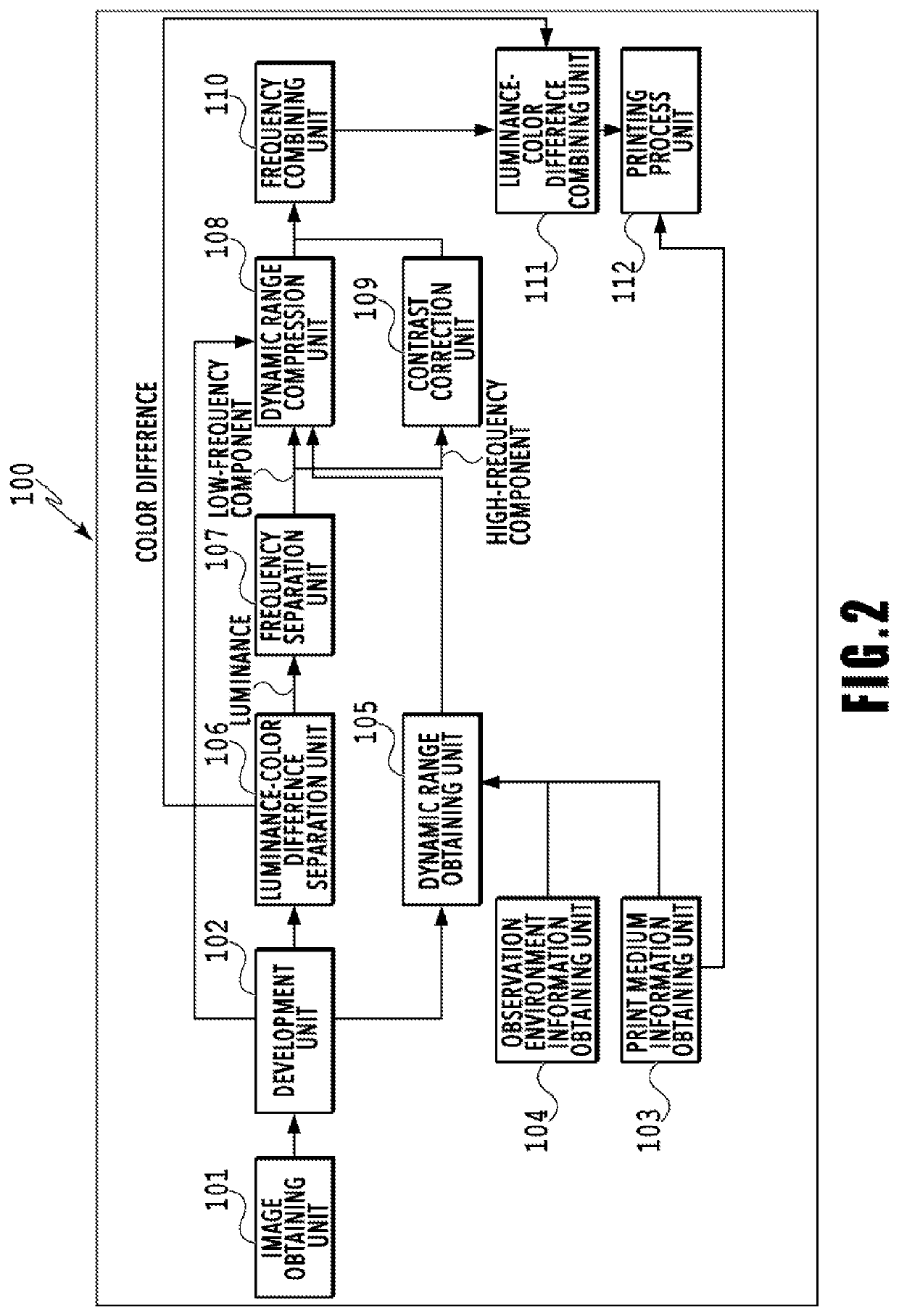
[0091]In the present embodiment too, the image processing apparatus illustrated in FIGS. 1 and 2 is used, ...


PUM


Abstract

An image processing apparatus has a dynamic range compression unit that converts an input luminance signal included in a developed data into an output luminance signal by using a conversion parameter. The unit obtains an input black reference luminance value and an input white reference luminance value of the luminance information included in the developed data. The unit, on a basis of print medium information and observation environment information, obtains an output black reference luminance value and an output white reference luminance value and calculates a reference output luminance value for observation. The unit generates a conversion line and generates the conversion parameter by using the conversion line. The conversion line indicating a correspondence between the input luminance signal and the output luminance signal.

Description

BACKGROUND OF THE INVENTIONField of the Invention[0001]The present invention relates to an image processing apparatus and an image processing method for printing a captured image.Description of the Related Art[0002]In image capture devices such as digital cameras, the luminance range of light which their sensors for converting light into signals can receive has been becoming wider. Thus, a high-luminance region that would be saturated with a conventional technique (highlight-detail loss) can now be obtained as information with a tonality. There has also been a progress in techniques for widening the reproduction range in development processes performed to reproduce image data received from an image capture device on another device. For example, Japanese Patent Laid-Open No. 2015-156615 discloses a method involving: calculating a saturation level for each color signal of image data received from an image capture device; and adjusting the dynamic range so as to prevent loss of the ton...

Claims


Application Information

Patent Timeline
Patent Type & Authority Applications(United States)
IPC IPC(8): H04N1/407H04N1/00G06K15/10G06K15/02
CPCH04N1/00188G06K15/102G06K15/1872H04N1/4074H04N1/00172G06K15/1878G06K15/027
Inventor SUWA, TETSUYAKAGAWA, HIDETSUGUWADA, SATOSHIYOSHIZAWA, KEI
Owner CANON KK
Why Eureka
Try Eureka