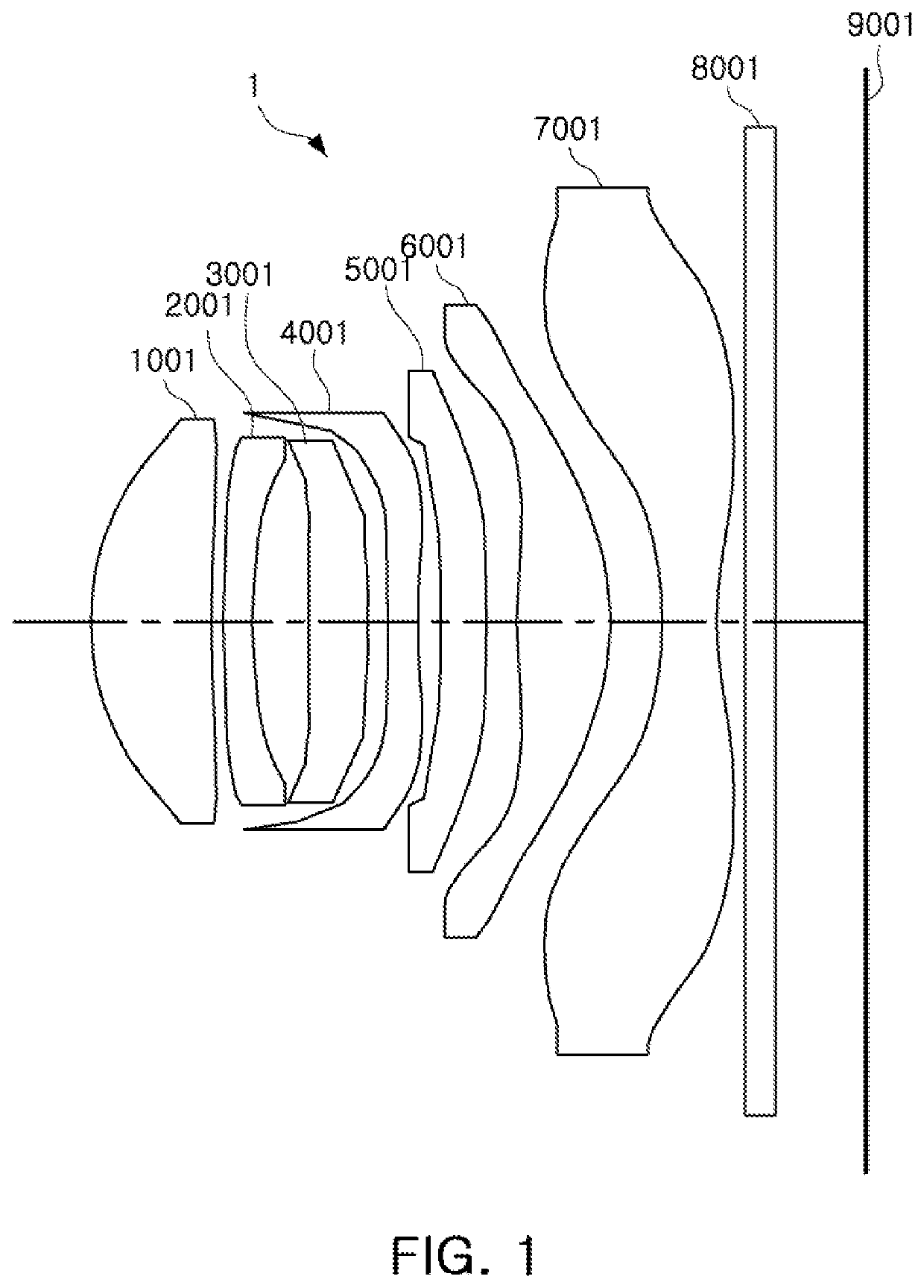
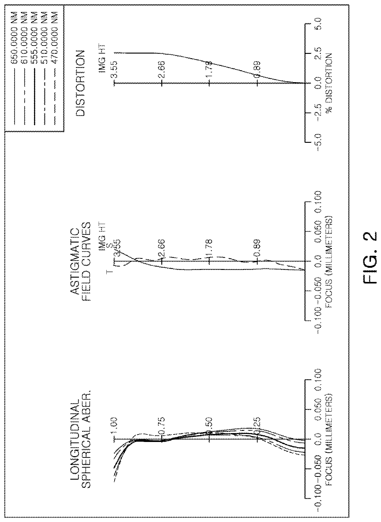
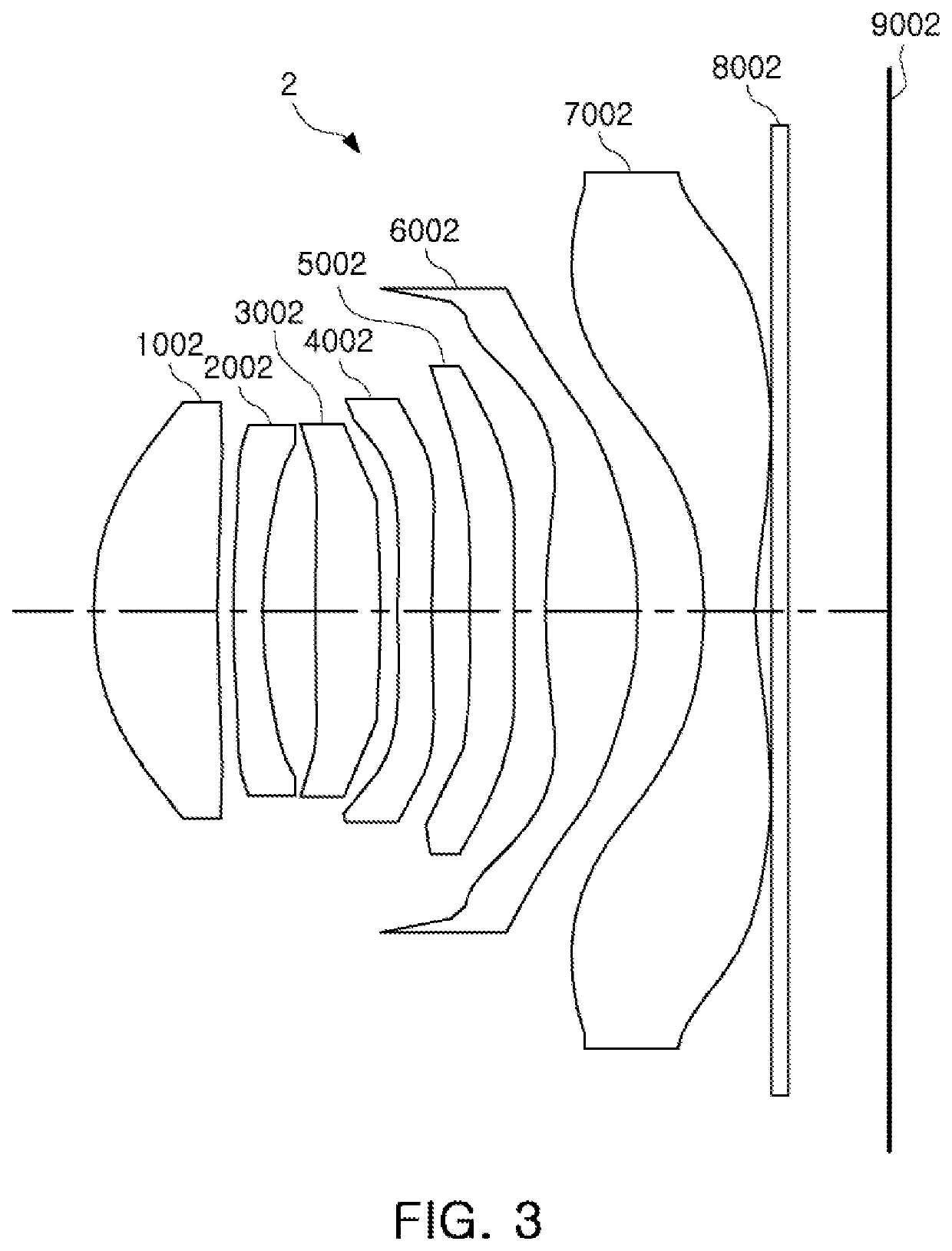
Optical imaging system
a technology of optical imaging and optical imaging, applied in the field of optical imaging systems, can solve the problems of difficult to achieve high performance in such a camera for a mobile terminal
- Summary
- Abstract
- Description
- Claims
- Application Information
AI Technical Summary
Benefits of technology
Problems solved by technology
Method used
Image
Examples
tenth example
[0196]FIG. 19 is a view illustrating a tenth example of an optical imaging system, and FIG. 20 illustrates aberration curves of the optical imaging system of FIG. 19.
[0197]An optical imaging system 10 includes a first lens 1010, a second lens 2010, a third lens 3010, a fourth lens 4010, a fifth lens 5010, a sixth lens 6010, and a seventh lens 7010.
[0198]The first lens 1010 has a positive refractive power, a convex object-side surface, and a concave image-side surface. The second lens 2010 has a negative refractive power, a convex object-side surface, and a concave image-side surface. The third lens 3010 has a negative refractive power, a convex object-side surface, and a concave image-side surface. The fourth lens 4010 has a positive refractive power, a convex object-side surface, and a concave image-side surface. The fifth lens 5010 has a negative refractive power, a concave object-side surface, and a convex image-side surface. The sixth lens 6010 has a positive refractive power, a...
twelfth example
[0207]FIG. 23 is a view illustrating a twelfth example of an optical imaging system, and FIG. 24 illustrates aberration curves of the optical imaging system of FIG. 23.
[0208]An optical imaging system 12 includes a first lens 1012, a second lens 2012, a third lens 3012, a fourth lens 4012, a fifth lens 5012, a sixth lens 6012, and a seventh lens 7012.
[0209]The first lens 1012 has a positive refractive power, a convex object-side surface, and a concave image-side surface. The second lens 2012 has a positive refractive power, a convex object-side surface, and a convex image-side surface. The third lens 3012 has a negative refractive power, a convex object-side surface, and a concave image-side surface. The fourth lens 4012 has a negative refractive power, a convex object-side surface, and a concave image-side surface. The fifth lens 5012 has a positive refractive power, a convex object-side surface, and a concave image-side surface. The sixth lens 6012 has a negative refractive power, ...
thirteenth example
[0212]FIG. 25 is a view illustrating a thirteenth example of an optical imaging system, and FIG. 26 illustrates aberration curves of the optical imaging system of FIG. 25.
[0213]An optical imaging system 13 includes a first lens 1013, a second lens 2013, a third lens 3013, a fourth lens 4013, a fifth lens 5013, a sixth lens 6013, and a seventh lens 7013.
[0214]The first lens 1013 has a positive refractive power, a convex object-side surface, and a concave image-side surface. The second lens 2013 has a positive refractive power, a convex object-side surface, and a concave image-side surface. The third lens 3013 has a negative refractive power, a convex object-side surface, and a concave image-side surface. The fourth lens 4013 has a positive refractive power, a convex object-side surface, and a concave image-side surface. The fifth lens 5013 has a negative refractive power, a convex object-side surface, and a concave image-side surface. The sixth lens 6013 has a positive refractive pow...
PUM
 Abstract
Description
Claims
Application Information
 - R&D
- Intellectual Property
- Life Sciences
- Materials
- Tech Scout
- Unparalleled Data Quality
- Higher Quality Content
- 60% Fewer Hallucinations
Browse by: Latest US Patents, China's latest patents, Technical Efficacy Thesaurus, Application Domain, Technology Topic, Popular Technical Reports.
© 2025 PatSnap. All rights reserved.Legal|Privacy policy|Modern Slavery Act Transparency Statement|Sitemap|About US| Contact US: help@patsnap.com


