
Face scanning and positioning structure used for full denture

a positioning structure and full denture technology, applied in the field of face scanning and positioning structure, can solve the problems of large positioning error of the y-axis, affecting the accuracy and quality of denture production, and complete loss of teeth, so as to reduce the image overlay error of a specific axis, improve the applicability and quality of denture products

Inactive Publication Date: 2019-12-12
CHIOU WEN HSIN +1
View PDF2 Cites 3 Cited by
  • Summary
  • Abstract
  • Description
  • Claims
  • Application Information

AI Technical Summary

Benefits of technology

The present invention aims to provide a structure for scanning and positioning a patient's face when making a full denture. This structure helps to reduce the "image overlay error" of a specific axis, making it easier to see and address any issues with the denture's fit. This results in improved quality and usability of the dental products.

Problems solved by technology

The demand for making a full denture is common for elderly patients or those who suffer from bad habits (such as smoking, eating betel nut, etc.), resulting in complete loss of teeth.
Due to the coincidence of the 3D image after scanning, the positioning error of the Y-axis is large.
The design of the planar black point is easy to present an incomplete image for the triangular mesh point 3D image, which affects the accuracy and quality of the denture production.

Method used


Image

  • Face scanning and positioning structure used for full denture
  • Face scanning and positioning structure used for full denture
  • Face scanning and positioning structure used for full denture

Examples


Embodiment Construction

[0012]Embodiments of the present invention will now be described, by way of example only, with reference to the accompanying drawings.

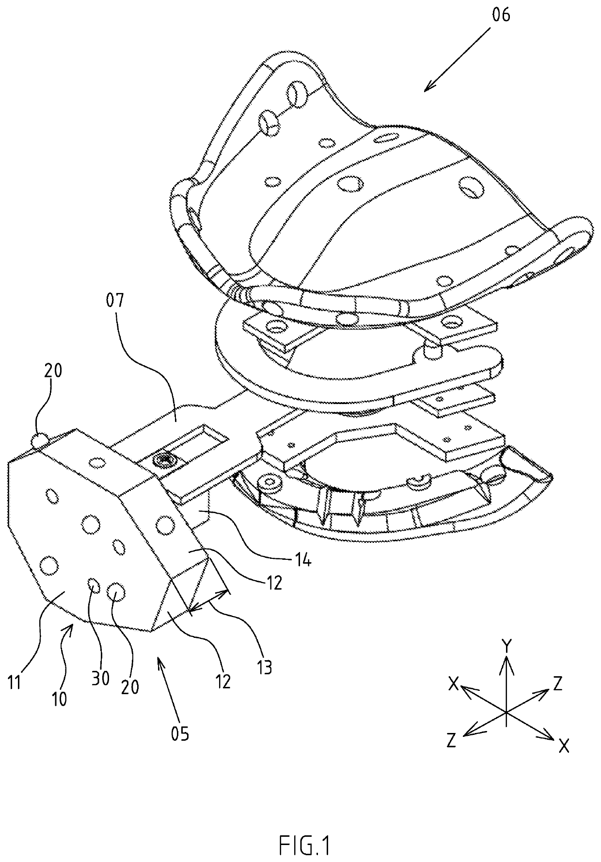
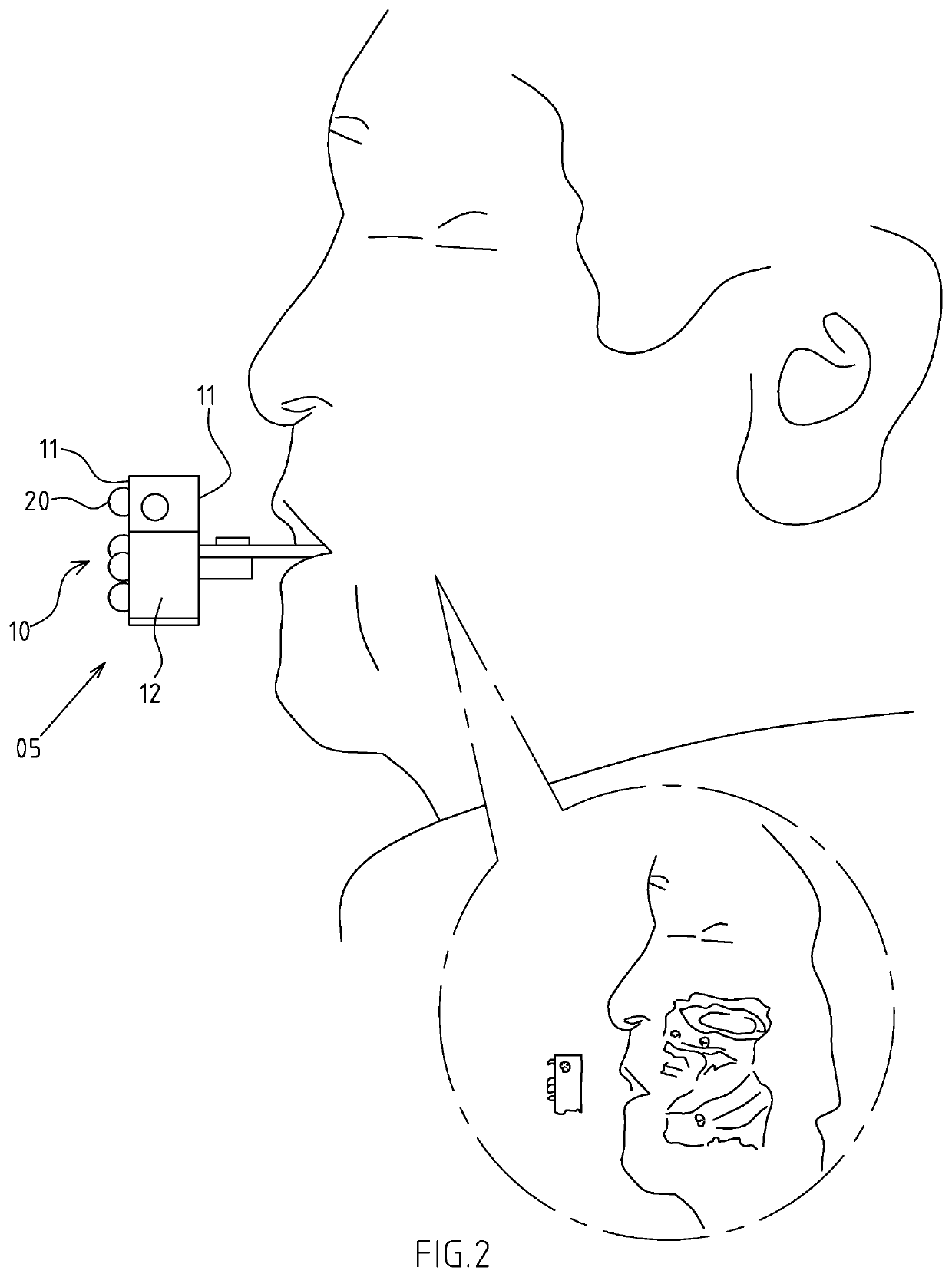
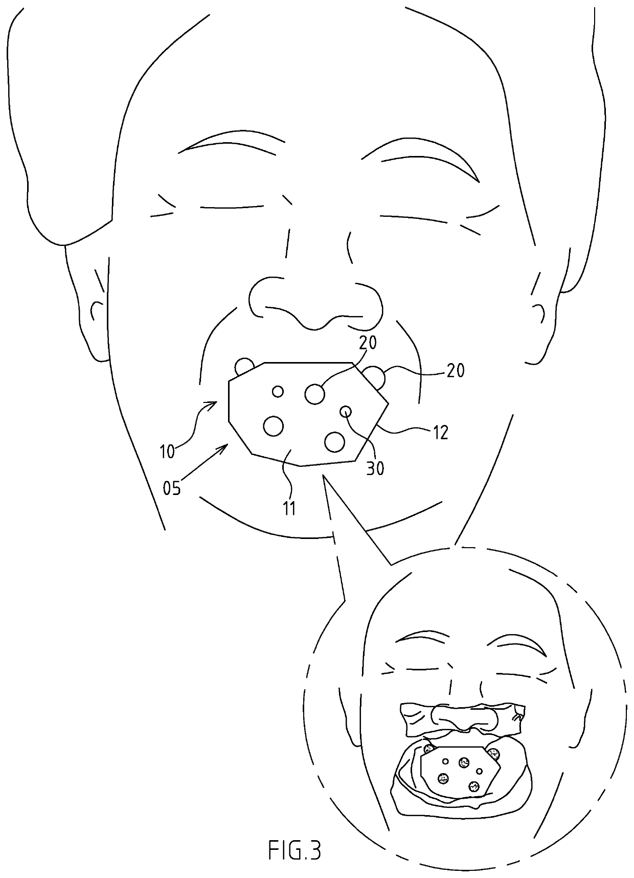
[0013]Firstly, referring to FIG. 1 to FIG. 3, the present invention provides a face scanning and positioning structure 05 used for a full denture. The face scanning and positioning structure 05 is cooperatively installed to a universal intermaxillary relationship recording device 06. The face scanning and positioning structure 05 comprises an irregularly shaped body 10, a plurality of development projections 20, and a plurality of concave portions 30.

[0014]The irregularly shaped body 10 defines an asymmetrical face portion 11 along an X-axis (only shown in FIG. 1), an asymmetrical side portion 12 along a Y-axis (only shown in FIG. 1), and a thickness 13 along a Z-axis (only shown in FIG. 1). The asymmetrical face portion 11 and the asymmetrical side portion 12 are in the form of an asymmetrical structure. One side of the asymmetrical face portion 11 i...


PUM


Abstract

A face scanning and positioning structure used for a full denture includes an irregularly shaped body, development projections, and concave portions. The irregularly shaped body defines an asymmetrical face portion along an X-axis, an asymmetrical side portion along a Y-axis, and a thickness along a Z-axis. The development projections are arranged on the asymmetrical face portion and the asymmetrical side portion at predetermined positions. The development projections protrude outwardly. The concave portions are arranged on the asymmetrical face portion and the asymmetrical side portion at predetermined positions. The concave portions each have a concave shape. Through the development projections and the concave portions, the irregularly shaped body is in the form of an asymmetrical structure along the X-axis, the Y-axis, and the Z-axis. Through the irregular protrusions and concave portions, the face scanning and positioning structure can effectively reduce the image overlay error of a specific axis.

Description

FIELD OF THE INVENTION[0001]The present invention relates to a face scanning and positioning structure, and more particularly to a face scanning and positioning structure used for a full denture.BACKGROUND OF THE INVENTION[0002]The demand for making a full denture is common for elderly patients or those who suffer from bad habits (such as smoking, eating betel nut, etc.), resulting in complete loss of teeth. The most common full denture is in the form of a movable denture, which usually includes a whole set of maxillary teeth and mandibular teeth. Before making a full denture or a denture restoration design, it is necessary to record the dynamic intermaxillary relationship to ensure the suitability and comfort of the products. Recording the dynamic intermaxillary relationship for a patient without any tooth is to record the so-called Gothic arch movement path. After the dynamic intermaxillary relationship is recorded, when a 3D scanner is used to scan the patient's face, it is neces...

Claims


Application Information

Patent Timeline
Patent Type & Authority Applications(United States)
IPC IPC(8): A61C9/00A61B6/14A61B6/51
CPCA61C9/004A61B6/14A61B2090/3966A61B90/39A61C19/05A61B6/032A61B2090/3983A61B6/51
Inventor CHIOU, WEN-HSINTSAI, JHEN-GUO
Owner CHIOU WEN HSIN
Learn More