Injection mold
- Summary
- Abstract
- Description
- Claims
- Application Information
AI Technical Summary
Benefits of technology
Problems solved by technology
Method used
Image


Examples
Embodiment Construction
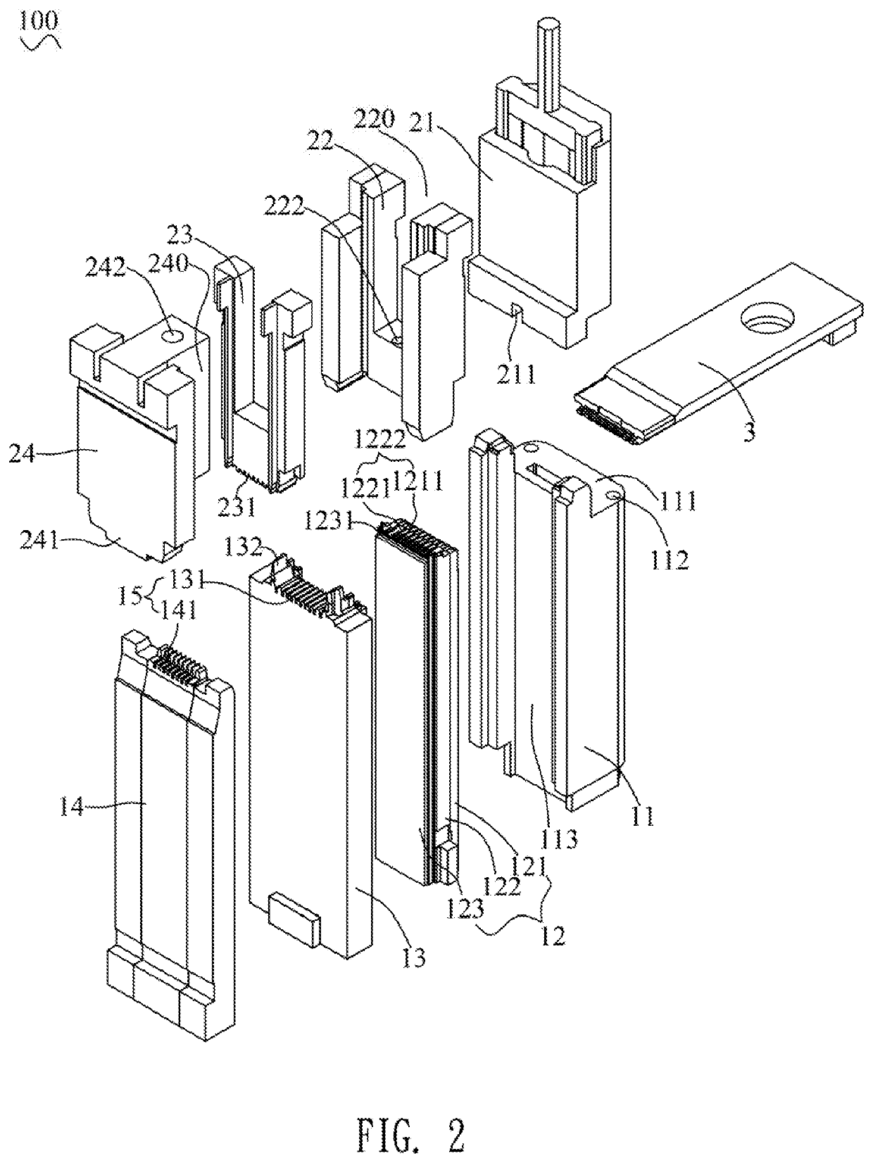
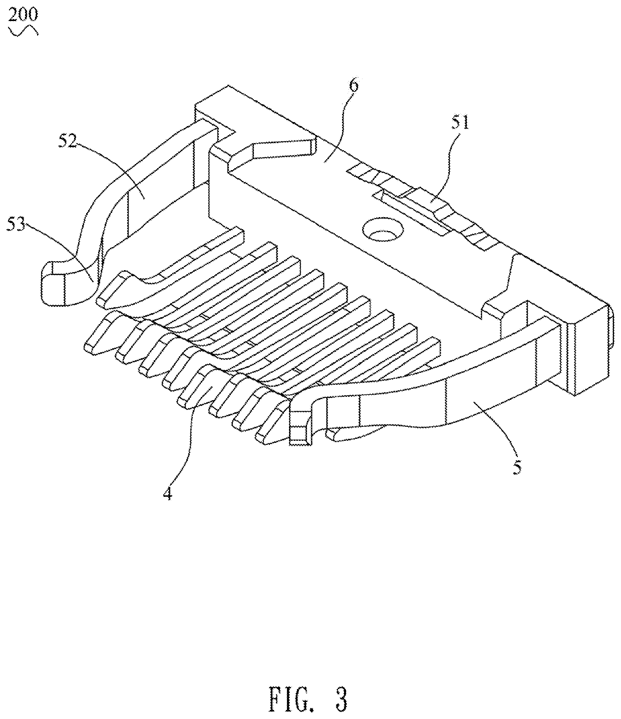
[0023]With reference to FIG. 1, an injection mold 100 in accordance with a preferred embodiment of the present invention is shown. The injection mold 100 adapted for molding an electrical connector assembly 200, includes a lower mold 1, an upper mold 2, and a filling block 3 cooperating with the lower mold 1 and the upper mold 2.
[0024]With reference to FIG. 2 and FIG. 8, a top of the lower mold 1 has a plurality of lower terminal grooves 15 recessed downward. Two sides of the top of the lower mold 1 protrude upward to form two limiting blocks 132. A substantial middle of the top of the lower mold 1 is recessed downward to form a lower cavity 16. A rear of a top surface of the lower mold 1 is defined as an accommodating surface 111. The lower mold 1 defines a plurality of limiting slots 1222 penetrating through the top surface of the lower mold 1. The lower mold 1 includes a first lower molding block 11, a second lower molding block 12, a third lower molding block 13 and a fourth low...
PUM
 Abstract
Description
Claims
Application Information