Optical membrane switch device

Active Publication Date: 2020-01-30
CHICONY ELECTRONICS
View PDF0 Cites 1 Cited by
  • Summary
  • Abstract
  • Description
  • Claims
  • Application Information

AI Technical Summary

Benefits of technology

The patent describes an optical membrane switch device that does not require electric circuits and is water-proof. It uses first and second membrane layers with light input and output lines. The membrane layers are clamped together with a spacer layer that has through holes. The first and second membrane layers have slanting lines that form contact regions where light can be transmitted. When the contact regions are pressed, the first and second branches lines connect, allowing light to be transmitted from the input lines to the output lines. This design ensures that the keys are not degraded by abrasion or oxidation, and the strength of the press can be determined based on the contact area. The technical effects of this design include improved durability and reliability of the switch and better signal accuracy.

Problems solved by technology

Nonetheless, the conductive contacts are easy to abrade and oxidize and are easily affected by dust, such that the sensitivity of the keys degrades.
In addition, conventional keys are not water-proofed; therefore, the typing quality of keyboards is significantly lower.
As a result, the issue of ghost key may occur.

Method used


Image

  • Optical membrane switch device
  • Optical membrane switch device
  • Optical membrane switch device

Examples


Embodiment Construction

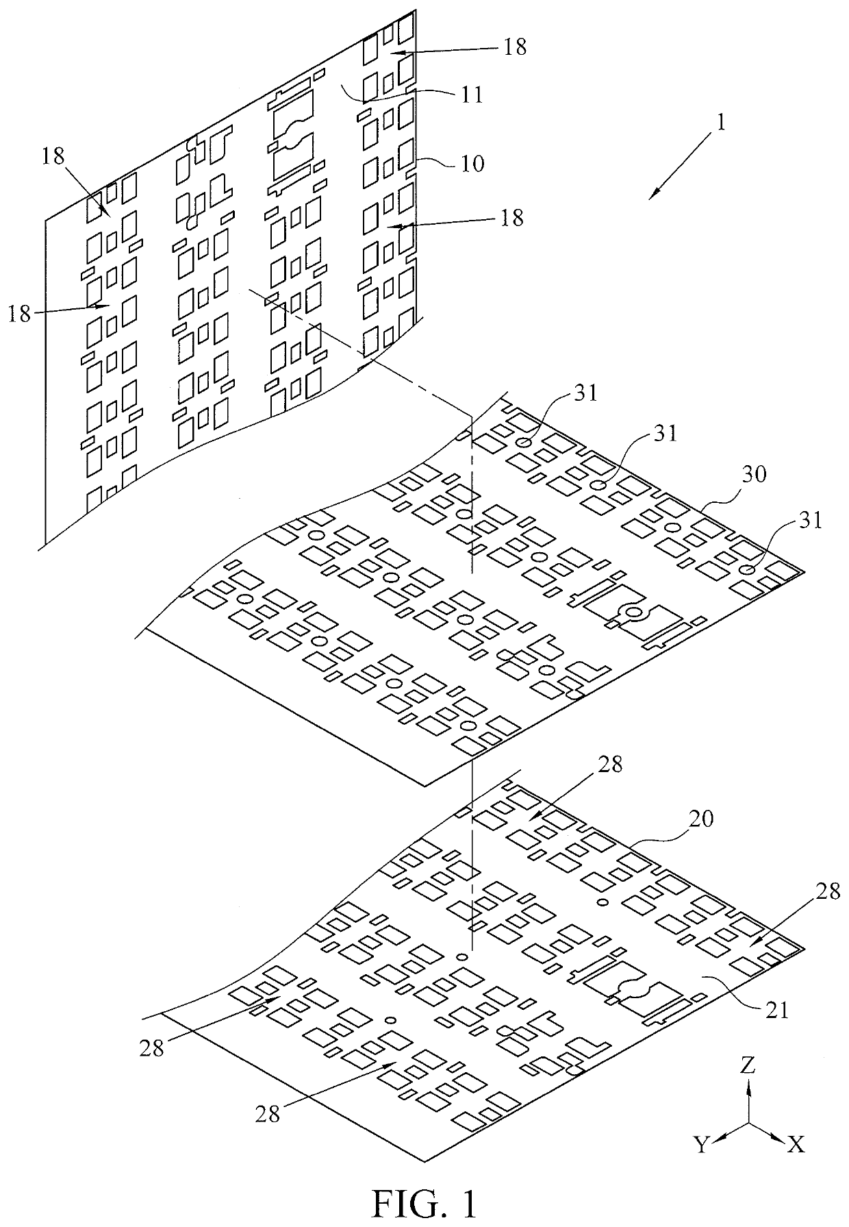
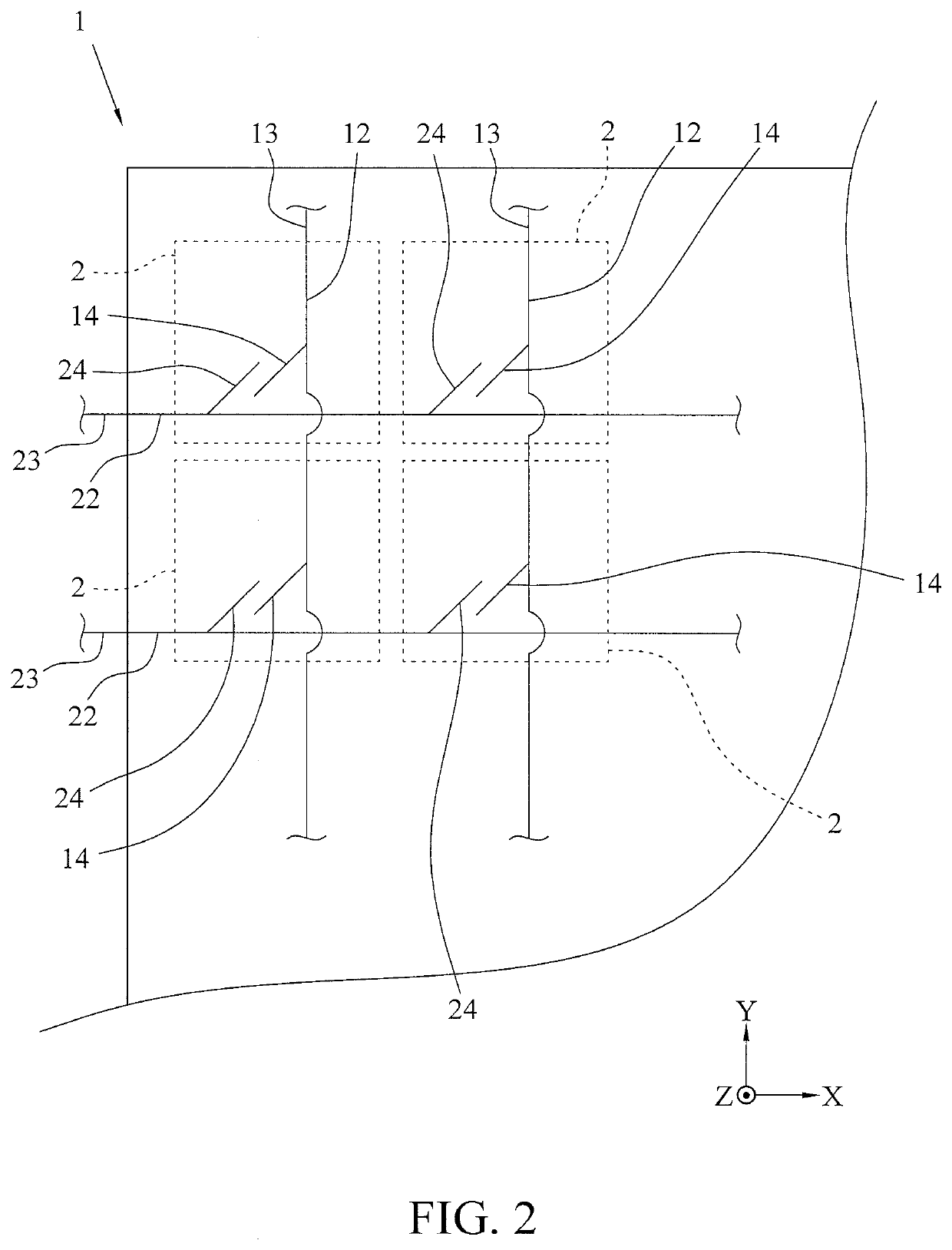
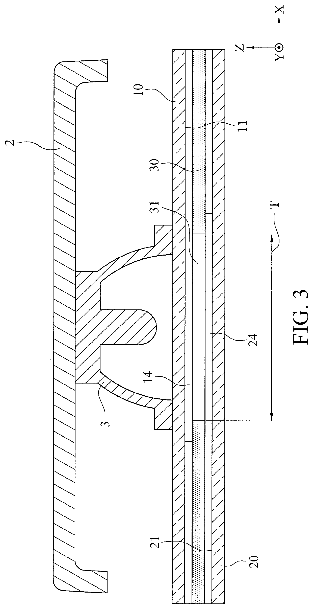
[0019]FIG. 1 is an exploded view of an optical membrane switch device according to an embodiment of the instant disclosure. FIG. 2 is a partially schematic diagram of lines of the optical membrane switch device according to an embodiment of the instant disclosure. FIG. 3 illustrates a partially cross sectional view of the optical membrane switch device according to an embodiment of the instant disclosure.

[0020]As shown in FIG. 1 to FIG. 3, an optical membrane switch device 1 is a multi-layer membrane structure, comprising a first membrane layer 10, a second membrane layer 20, and a spacer layer 30. In the embodiment, the optical membrane switch device 1 as a whole can be rectangular, square, circular, or irregular depending on the shape of an actual product. For example, in the embodiment, the optical membrane switch device 1 is applied to a computer keyboard and thus is, but not limited to, rectangular depending on the shape of the computer keyboard.

[0021]As shown in FIG. 1, in the...


PUM


Abstract

An optical membrane switch device includes a first membrane layer, a second membrane layer, and a spacer layer. The first membrane layer includes a first surface and light input lines. The light input lines are disposed on the first surface. Each light input line is slantingly extended with first branch lines. The second membrane layer includes a second surface and light output lines. The light output lines are disposed on the second surface. Each light output line is slantingly extended with second branch lines. The second branch lines respectively extend to the corresponding first branch lines to form contact regions. The spacer layer is clamped between the first membrane layer and the second membrane layer and includes through holes respectively corresponding to the contact regions. The first and second branch lines corresponding to the through holes at least partially overlap each other and keep a preset interval from each other.

Description

CROSS-REFERENCE TO RELATED APPLICATION[0001]This non-provisional application claims priority under 35 U.S.C. § 119(a) to Patent Application No. 107125795 filed in Taiwan, R.O.C. on Jul. 25, 2018, the entire contents of which are hereby incorporated by reference.BACKGROUNDTechnical Field[0002]The instant disclosure relates to a switch device and, more particularly, to an optical membrane switch device.Related Art[0003]Keyboards are very common input devices, which are usually used along with electronic devices such as desktop computers, laptop computers, smart phones, or tablet computers. The development of electronic devices trends towards a light, compact design. Correspondingly, most of keyboards adopt membrane switches, which are small, thin, and light.[0004]In general, a membrane switch is mainly consisted of three overlapped membrane layers. Opposite surfaces of upper and lower membranes are printed with conductive lines and conductive contacts. The conductive contacts correspo...

Claims


Application Information

Patent Timeline
IPC IPC(8): G06F3/02G02B5/20F21V8/00G02B6/35
CPCG02B6/354G02B5/20G02B6/0021G06F3/0202G02B6/283G02B6/3502G02B6/3556G02B6/3574G02B6/3596
Inventor CHEN, CHIEN-TSUNG
Owner CHICONY ELECTRONICS
Why Eureka
Try Eureka