Lens characteristic evaluation device and method of operating lens characteristic evaluation device

Active Publication Date: 2019-03-28
KK TOPCON
View PDF5 Cites 0 Cited by
  • Summary
  • Abstract
  • Description
  • Claims
  • Application Information

AI Technical Summary

Benefits of technology

The invention relates to a device that evaluates the quality of a captured image. The technical effect of the device is that it prevents degraded sensitivity in detecting point images in both the center and peripheral portions of the image, while also preventing whiteout (saturation) of certain images. This is achieved without increasing the size of the device.

Problems solved by technology

In the meantime, as in the lens characteristic evaluation devices disclosed in Japanese Patent Application Laid-Open No. 2005-274473 and Japanese Patent Application Laid-Open No. 2006-275971, when the screen is moved, a problem arises that the size of the lens characteristic evaluation device becomes large because a movement mechanism for moving the screen is provided.
Also, when the screen is moved, it is susceptible to the influence of the reproducibility of the moving distance.

Method used


Image

  • Lens characteristic evaluation device and method of operating lens characteristic evaluation device
  • Lens characteristic evaluation device and method of operating lens characteristic evaluation device
  • Lens characteristic evaluation device and method of operating lens characteristic evaluation device

Examples


second embodiment

Lens Characteristic Evaluation Device

[0131]FIG. 13 is a functional block diagram of an integrated control unit 58 of a lens characteristic evaluation device 10A according to the second embodiment. This lens characteristic evaluation device 10A according to the second embodiment has functions for carrying out setting of the scanning range and the scanning pattern of the linear luminous flux 46, and adjustment of the number of point images formed by the linear luminous flux 46 and included in one frame of the captured image 52.

[0132]As illustrated in FIG. 13, the lens characteristic evaluation device 10A according to the second embodiment has basically the same configuration as that of the lens characteristic evaluation device 10 according to the first embodiment, apart from the feature that the integrated control unit 58 functions as a scan setting unit 88 and a point image number adjustment unit 90. As a result, the same reference numerals and / or characters are given to those having...

third embodiment

[0141]Next, explanations will be provided herein on the lens characteristic evaluation device 10B according to the third embodiment (see FIG. 15). The scanner 42 in the above-described embodiments adjusts the scan angle of the linear luminous flux 46 by adjusting the swing angles θ, φ of the respective Galvano minors 42A such that linear luminous flux 46 is emitted for scanning in the two-dimensional directions. Note that the scan angle of the linear luminous flux 46 (which may also be referred to as an emission angle) is an angle of the linear luminous flux 46 emitted from the scanner 42, for example, if the respective. Galvano minors 42A are disposed at the swing center positions, i.e., an angle with reference to the reference direction that is parallel to the linear luminous flux 46 at the scanning center position of the scanner 42 (indicated by the dash-dotted line in FIG. 15) (the angle in the xy directions in FIG. 15).

[0142]In the course of this, in a certain type of the scann...

fourth embodiment

[0164]FIG. 18 is a functional block diagram of the lens characteristic evaluation device 10C according to the fourth embodiment. In this lens characteristic evaluation device 10C according to the fourth embodiment, the optical characteristic (mapping image) of the spectacle lens 102 is obtained using the measured values of the swing angles θ, φ of the respective Galvano mirrors 42A acquired by the measured value acquisition unit 410 explained in the third embodiment.

[0165]As illustrated in FIG. 18, the lens characteristic evaluation device 10C according to the fourth embodiment has basically the same configuration as that of the lens characteristic evaluation device 10B according to the third embodiment, apart from the fact that the integrated control unit 58 does not function as the correction unit 412 of the third embodiment (see FIG. 16) and the optical characteristic acquisition unit 70 functions as the mapping image generation unit 416. Therefore, the same reference numerals an...


PUM


Abstract

A lens characteristic evaluation device includes: a scanning optical system configured to scan a surface of a test lens with a linear luminous flux; a Hartmann plate provided on a side opposite to the scanning optical system with respect to the test lens and having a plurality of two-dimensionally arranged pinholes, the Hartmann plate being configured to transmit the linear luminous flux which has passed through the test lens and radiated on the pinholes by the scanning performed by the scanning optical system; a screen on which the linear luminous flux having passed through the Hartmann plate is projected; and a photographing optical system provided on a side opposite to the Hartmann plate with respect to the screen and configured to photograph the screen while the scanning with the linear luminous flux is being performed by the scanning optical system.

Description

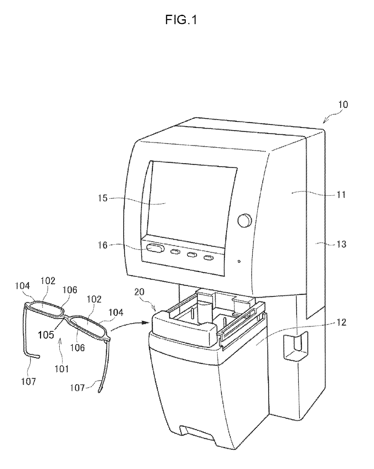
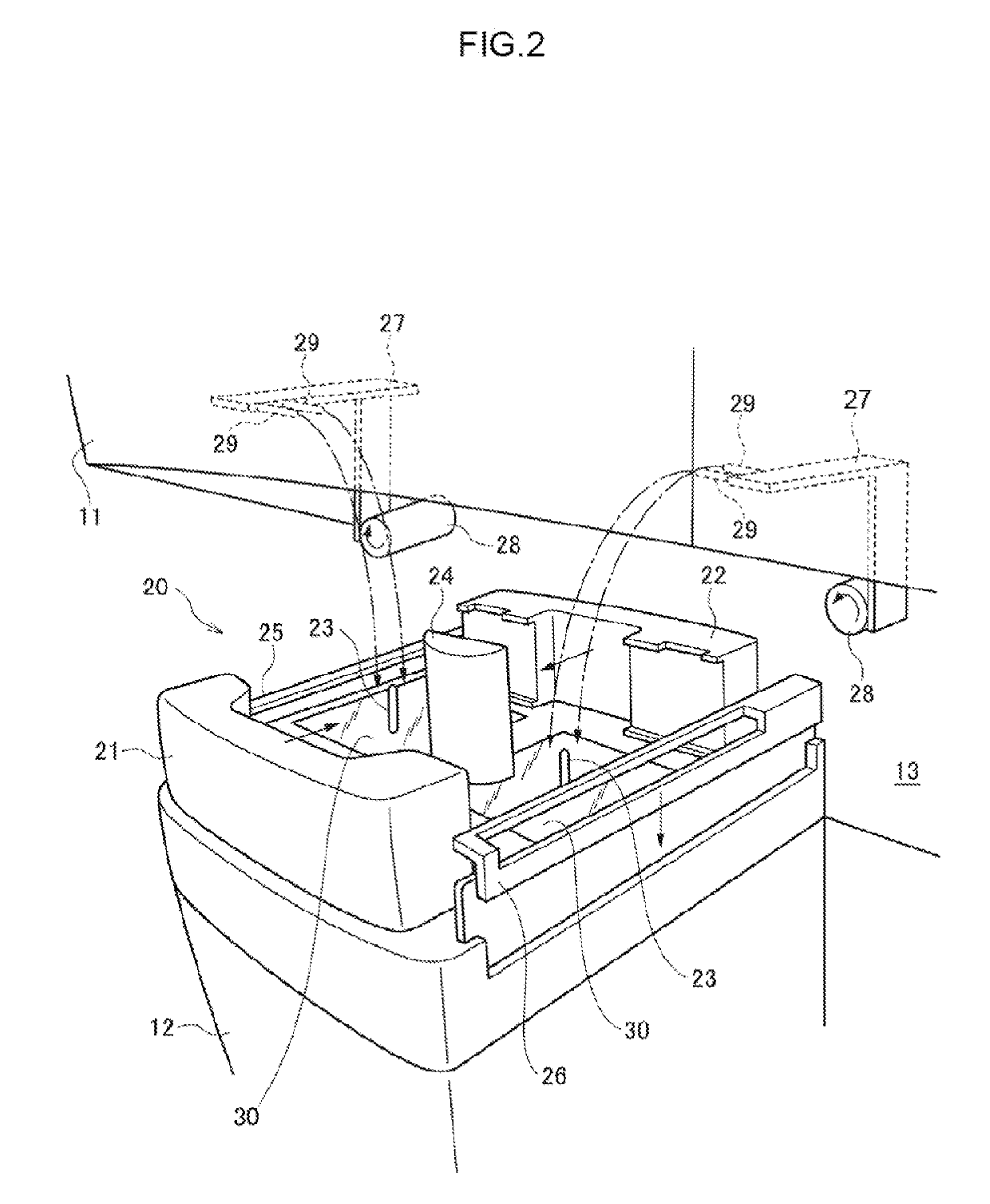
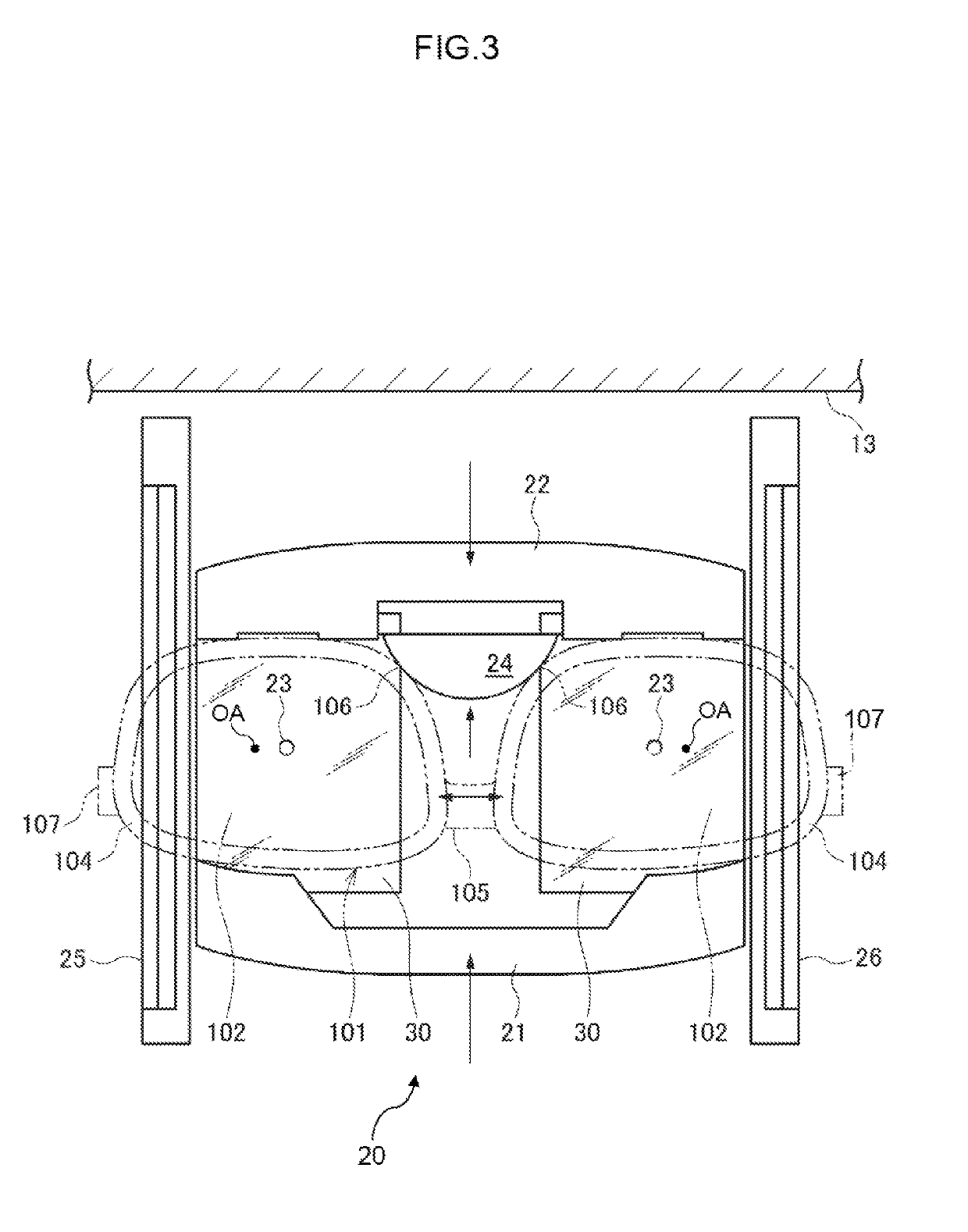
CROSS-REFERENCE TO RELATED APPLICATION[0001]The present application claims priorities under 35 U.S.C. § 119 to Japanese Patent Application No. 2017-185272, filed on Sep. 26, 2017 and Japanese Patent Application No. 2018-135146, filed on Jul. 18, 2018. Each of the above applications is hereby expressly incorporated by reference, in its entirety, into the present application.BACKGROUND OF THE INVENTIONField of the Invention[0002]The present invention relates to a lens characteristic evaluation device that evaluates optical characteristics of a test lens (lens to be tested) and a method of operating the lens characteristic evaluation device.Description of the Related Art[0003]A lens characteristic evaluation device is brown that evaluates an optical characteristic of a spectacle lens (test lens). The lens characteristic evaluation device includes: an illumination optical system which irradiates the test lens with a measuring light consisting of parallel luminous flux having a light flu...

Claims


Application Information

Patent Timeline
IPC IPC(8): G01M11/02G02B26/10
CPCG01M11/0207G02B26/101G01M11/02G01M11/0264
Inventor SAIKA, MAKOTO
Owner KK TOPCON
Why Eureka
Try Eureka