

Reel seat for fishing rod, fishing rod, and movable hood for reel
- Summary
- Abstract
- Description
- Claims
- Application Information
AI Technical Summary
Benefits of technology
Problems solved by technology
Method used
Image

Examples
first embodiment
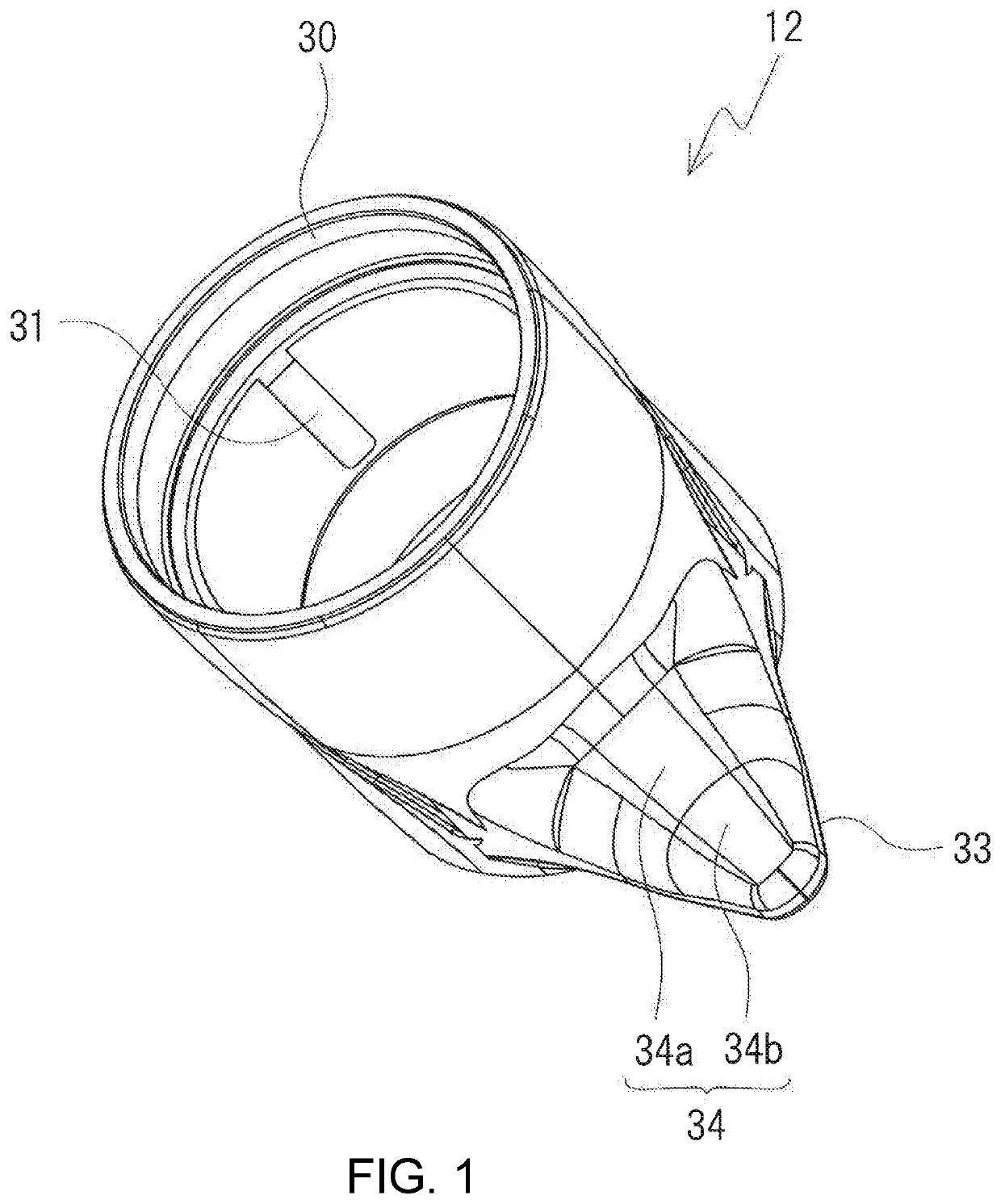
[0044]A movable hood, a reel seat for a fishing rod comprising same, and a fishing rod according to a first embodiment of the present invention will be described below with reference to FIGS. 1 to 13. A reel seat 2 according to the present embodiment is for fixing a reel to a fishing rod and is used by attachment to a rod body 1 (blank) of the fishing rod. The reel seat 2 is a so-called pipe seat, which has an overall tubular shape and is externally mounted on the rod body 1 and adhesively fixed in a prescribed position. The reel may be a spinning reel or a dual-bearing reel 3. The reel comprises a reel foot (refer to FIG. 8) that extends in the longitudinal direction. The reel is fixed to the fishing rod by fixing the reel foot to the reel seat 2.
[0045]In one embodiment, FIG. 10 shows a state in which the dual-bearing reel 3 is attached to the reel seat 2 of the fishing rod. The dual-bearing reel 3 is normally attached to the upper side of the reel seat 2. The rod tip side is refer...
second embodiment
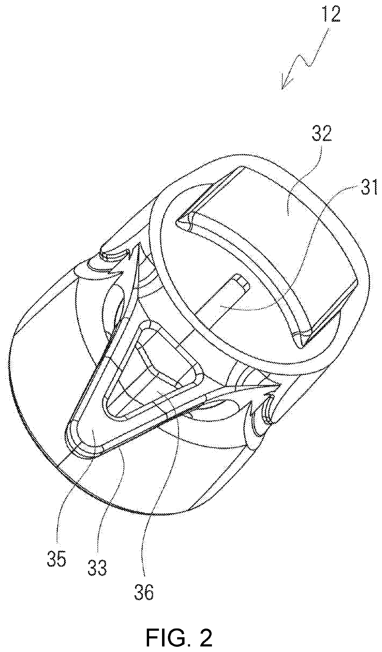
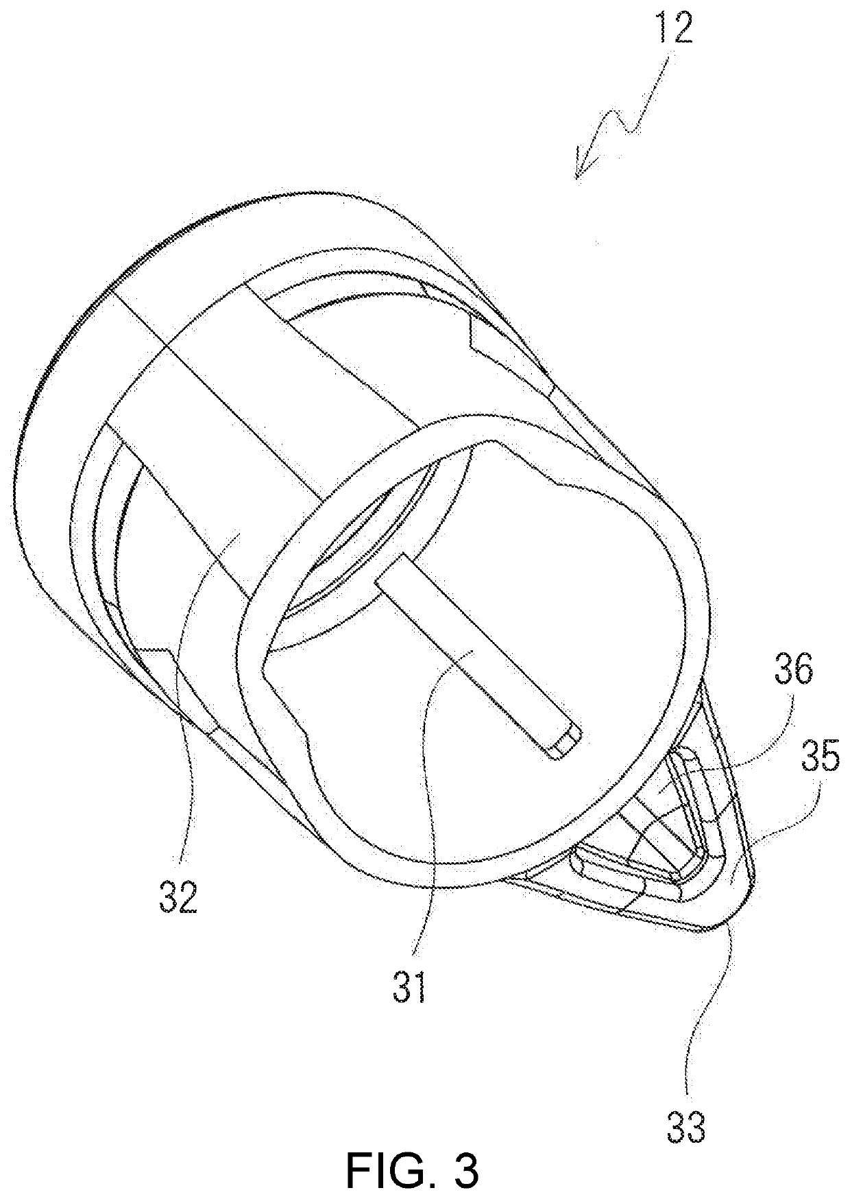
[0070]The movable hood 12, the reel seat 2, and the fishing rod according to a second embodiment will now be described. However, detailed descriptions of configurations that are the same as in the first embodiment will be omitted. The movable hood 12 according to the second embodiment is shown as a single unit in FIGS. 14 to 21C. The movable hood 12 according to the second embodiment has a pair of engagement ridges 31 on the left and right. In addition, in the movable hood 12 shown in FIGS. 16 and 20, the trigger 33 is positioned more forward compared with the movable hood 12 according to the first embodiment. The trigger 33 is positioned essentially in the central portion of the movable hood 12 in the longitudinal direction. A crest portion 34c, with a smaller radius of curvature than the other portions, extends along the longitudinal direction in the central portion of the front surface 34 of the trigger 33 in the left-right direction (central portion in the width direction). The ...
PUM
 Abstract
Description
Claims
Application Information